127
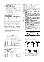
The temperature of condensate drainage water
is very low. If insulation is not enough, it shall
form dew and cause leakage to damage the
house decoration.
3
Insulation material selection for
drainage pipe
The insulation material should be flame
retardant material, the flame retardancy of
the material should be selected according
to the local law.
Thickness of insulation layer is usually
above 10mm.
Use specific glue to paste the seam of
insulation material, and then bind with
adhesive tape. The width of tape shall not
be less than 5cm. Make sure it is firm and
avoid dew.
4
Installation and highlights of insulation
construction
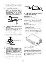
The single pipe should be insulated before
connecting to another pipe, the joint part
should be insulated after the drainage test.
There should be no insulation gap between
the insulation material.
13.9 Engineering of electrical wiring
1
Highlights of electrical wiring
installation
All field wiring construction should be
finished by qualified electrician.
Air conditioning equipment should be
grounded according to the local electrical
regulations.
Current leakage protection switch should
be installed.
Do not connect the power wire to the
terminal of signal wire.
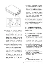
When power wire is parallel with signal wire,
put wires to their own wire tube and remain
at least 300mm gap.
According to table in indoor part named
“the specification of the power” to choose
the wiring, make sure the selected wiring
not small than the date showing in the
table.
Select different colors for different wire
according to relevant regulations.
Do not use metal wire tube at the place with
acid or alkali corrosion, adopt plastic wire
tube to replace it.
There must be not wire connect joint in the
wire tube If joint is a must, set a connection
box at the place.
The wiring with different voltage should not
be in one wire tube.
Ensure that the color of the wires of outdoor
and the terminal No. are same as those of
indoor unit respectively.
13.10 Test operation
1 The test operation must be carried out
after the entire installation has been
completed.
2
Please confirm the following points
before the test operation.
The indoor unit and outdoor unit are
installed properly.
Tubing and wiring are correctly completed.
The
refrigerant
pipe
system
is
leakage-checked.
The drainage is unimpeded.
The ground wiring is connected correctly.
The length of the tubing and the added
stow capacity of the refrigerant have been
recorded.
The power voltage fits the rated voltage of
the air conditioner.
There is no obstacle at the outlet and inlet
of the outdoor and indoor units.
The gas-side and liquid-side stop values
are both opened.
The air conditioner is pre-heated by turning
on the power.
3 Test operation
Set the air conditioner under the mode of
"COOLING" by remote controller, and check
the following points.
Indoor unit
Whether the switch on the remote controller
works well.
Whether the buttons on the remote
controller works well.
Whether the air flow louver moves
normally.
Whether the room temperature is adjusted
well.
Whether the indicator lights normally.
Whether the temporary buttons works well.
Summary of Contents for KDIP012-H2
Page 8: ...5 2 2 Part names of Indoor Outdoor units Cassette Units ...
Page 9: ...6 KDIR Duct Units ...
Page 10: ...7 KDIP Duct Units ...
Page 11: ...9 Ceiling floor Units ...
Page 12: ...10 HESP DUCT Units ...
Page 19: ...19 2 3 4 7 Outside Water Pump for Optional When Ceiling Installation ...
Page 31: ...33 KSIE024 H220 O KSIR036 H218 inch 37 2 16 1 31 9 40 6 26 5 15 9 ...
Page 34: ...36 Ceiling floor Units ...
Page 39: ...41 KTIR036 H2G1 KTIR048 H2G1 ...
Page 40: ...43 KUIR18 H2 KUIR24 H2 ...
Page 41: ...44 KFUF036 H2G1 KFUF048 H2G1 ...
Page 42: ...45 KFUF060 H2G1 ...
Page 43: ...46 KFUF036 H2G1 KFUF048 H2G1 ...
Page 44: ...47 KDIP090 H2 KDIP012 H2 KDIP018 H2 KDIP24 H2 ...
Page 69: ...74 6 2 Outdoor Unit KSIE018 H220 O KSIE024 H220 O ...
Page 70: ...75 KSIE009 H221 O KSIE012 H220 O ...
Page 71: ...77 KSIR036 H218 ...
Page 77: ...83 KDIR09 H2 Code 0 Code 1 Code 2 Code 3 Code 4 ...
Page 78: ...84 KDIR12 H2 Code 0 Code 1 Code 2 Code 3 Code 4 ...
Page 79: ...85 KDIR18 H2 Code 0 Code 1 Code 2 Code 3 Code 4 ...
Page 80: ...86 KDIR24 H2 Code 0 Code 1 Code 2 Code 3 Code 4 ...
Page 96: ...104 12 Field Wiring 9K 24K 36K 48K 60K ...
Page 97: ...105 ...
Page 147: ...155 P U P V ...
Page 148: ...156 P W P N ...
Page 181: ...191 4 Remove the evaporator fixing clamps to disassemble the evaporator Fixing clamps 1 screw ...
Page 188: ...221 5 Remove the four fixing screws of the fan motor then remove the motor 5 ...

