107
48.82
19.69
KDIP090-H2
/
KDIP012-H2
741
360
29.2
14.2
KDIP018-H2
920
508
36.22
20
KDIP24-H2
1140
598
44.88
23.54
KDIR036-H2G1
1400
598
55.12
23.54
KDIR048-H2G1
1240
697
48.82
27.44
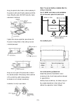
13.2.1.3 Hang indoor unit
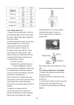
1. Please refer to the upper data to locate the
four positioning screw bolt hole on the ceiling.
Be sure to mark the areas where ceiling hook
holes will be drilled.
2. Install and fit pipes and wires after you have
finished installing the main body. When
choosing where to start, determine the
direction of the pipes to be drawn out.
Especially in cases where there is a ceiling
involved, align the refrigerant pipes, drain
pipes, and indoor and outdoor lines with their
connection points before mounting the unit.
3. Install hanging screw bolts.
• Cut off the roof beam.
• Strengthen the place that has been cut
off, and consolidate the roof beam.
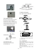
4. After you select an installation location, align
the refrigerant pipes, drain pipes, as well as
indoor and outdoor wires with their connection
points before mounting the unit.
5. Drill 4 holes 10cm (4”) deep at the ceiling
hook positions in the internal ceiling. Be sure to
hold the drill at a 90° angle to the ceiling.
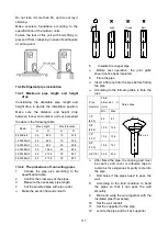
6. Secure the bolt using the washers and nuts
provided.
7. Install the four suspension bolts.
8. Mount the indoor unit with at least two
people to lift and secure it. Insert suspension
bolts into the unit’s hanging holes. Fasten
them using the washers and nuts provided.
9. Mount the indoor unit onto the hanging
screw bolts with a block. Position the
indoor unit flat using a level indicator to
prevent leaks.
Note: Confirm the minimum drain tilt is 1/100 or
more.
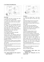
13.2.1.4 Duct and accessories installation
1. Install the filter (optional) according to the
size of the air inlet.
2. Install the canvas tie-in between the body
and the duct.
3. Air inlet and air outlet duct should be apart far
enough to avoid air passage short-circuit.
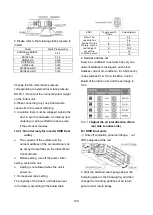
4. Connect the duct according to the following
diagram.
Summary of Contents for KDIP012-H2
Page 8: ...5 2 2 Part names of Indoor Outdoor units Cassette Units ...
Page 9: ...6 KDIR Duct Units ...
Page 10: ...7 KDIP Duct Units ...
Page 11: ...9 Ceiling floor Units ...
Page 12: ...10 HESP DUCT Units ...
Page 19: ...19 2 3 4 7 Outside Water Pump for Optional When Ceiling Installation ...
Page 31: ...33 KSIE024 H220 O KSIR036 H218 inch 37 2 16 1 31 9 40 6 26 5 15 9 ...
Page 34: ...36 Ceiling floor Units ...
Page 39: ...41 KTIR036 H2G1 KTIR048 H2G1 ...
Page 40: ...43 KUIR18 H2 KUIR24 H2 ...
Page 41: ...44 KFUF036 H2G1 KFUF048 H2G1 ...
Page 42: ...45 KFUF060 H2G1 ...
Page 43: ...46 KFUF036 H2G1 KFUF048 H2G1 ...
Page 44: ...47 KDIP090 H2 KDIP012 H2 KDIP018 H2 KDIP24 H2 ...
Page 69: ...74 6 2 Outdoor Unit KSIE018 H220 O KSIE024 H220 O ...
Page 70: ...75 KSIE009 H221 O KSIE012 H220 O ...
Page 71: ...77 KSIR036 H218 ...
Page 77: ...83 KDIR09 H2 Code 0 Code 1 Code 2 Code 3 Code 4 ...
Page 78: ...84 KDIR12 H2 Code 0 Code 1 Code 2 Code 3 Code 4 ...
Page 79: ...85 KDIR18 H2 Code 0 Code 1 Code 2 Code 3 Code 4 ...
Page 80: ...86 KDIR24 H2 Code 0 Code 1 Code 2 Code 3 Code 4 ...
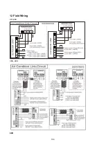
Page 96: ...104 12 Field Wiring 9K 24K 36K 48K 60K ...
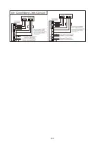
Page 97: ...105 ...
Page 147: ...155 P U P V ...
Page 148: ...156 P W P N ...
Page 181: ...191 4 Remove the evaporator fixing clamps to disassemble the evaporator Fixing clamps 1 screw ...
Page 188: ...221 5 Remove the four fixing screws of the fan motor then remove the motor 5 ...

