background image

52

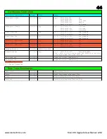
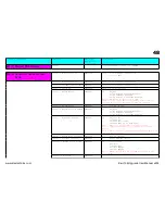
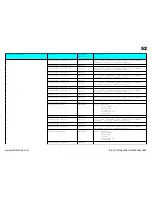
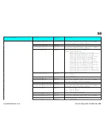
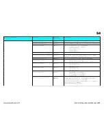
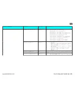
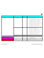
Table 1.0 Command ID

Data Byte

Data Type

Byte details
7 ------- 0

Data Details

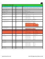
$37 (55)=Env 1 Sustain Lo

0yyyyyyy

Hi & Lo are combined to make single 12 bit command.

00 0yyyyyyy = 0000xxxx xyyyyyyy

$38 (56)=Env 1 Release Hi

000xxxxx

$39 (57)=Env 1 Release Lo

0yyyyyyy

Hi & Lo are combined to make single 12 bit command.
00 0yyyyyyy = 0000xxxx xyyyyyyy

$3a (58)=Env 2 Attack Hi

000xxxxx

$3b (59)=Env 2 Attack Lo

0yyyyyyy

Hi & Lo are combined to make single 12 bit command.

00 0yyyyyyy = 0000xxxx xyyyyyyy

$3c (60)=Env 2 Decay Hi

000xxxxx

$3d (61)=Env 2 Decay Lo

0yyyyyyy

Hi & Lo are combined to make single 12 bit command.
00 0yyyyyyy = 0000xxxx xyyyyyyy

$3e (62)=Env 2 Sustain Hi

000xxxxx

$3f (63)=Env 2 Sustain Lo

0yyyyyyy

Hi & Lo are combined to make single 12 bit command.

00 0yyyyyyy = 0000xxxx xyyyyyyy

$40 (64)=Env 2 Release Hi

000xxxxx

$41 (65)=Env 2 Release Lo

0yyyyyyy

Hi & Lo are combined to make single 12 bit command.
00 0yyyyyyy = 0000xxxx xyyyyyyy

$42 (66)=Env Control

Not used

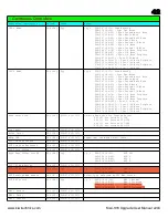
$43 (67)=LFO 1 Wave

000000xxx

xxx =

000=Sine

001=Triangle
010=Square

011=Saw
100=Reverse Saw

101=Random

$44 (68)=LFO 1 Rate Hi

000xxxxx

$45 (69)=LFO 1 Rate Lo

0yyyyyyy

Hi & Lo are combined to make single 12 bit command.
00 0yyyyyyy = 0000xxxx xyyyyyyy

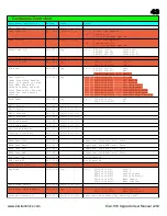
$46 (70)=LFO 1 Delay Hi

000xxxxx

$47 (71)=LFO 1 Delay Lo

0yyyyyyy

Hi & Lo are combined to make single 12 bit command.

00 0yyyyyyy = 0000xxxx xyyyyyyy

$48 (72)=LFO 2 Wave

000000xxx

xxx =

000=Sine
001=Triangle

010=Square
011=Saw

100=Reverse Saw
101=Random

$49 (73)=LFO 2 Rate Hi

000xxxxx

www.kiwitechnics.com

Kiwi-106 Upgrade User Manual v204

Summary of Contents for KIWI-106

Page 1: ......

Page 2: ...ders 11 VCA Slider 11 PWM Env Control 11 All Other Sliders Buttons 11 Kiwi 106 Menu System 12 Page Menus 12 Page 1 Arp 12 Page 2 Sequence 12 Page 3 Pattern 12 Page 4 Sysex Dumps 13 Page 5 Global Patch...

Page 3: ...illators 19 Master Clock 19 Factory Presets 19 Clock Display 19 Page Display Mode 20 LFO Display Mode 20 Midi Function Switch 20 Midi Received 20 Midi Panic 20 Note Hold 20 Edit Buffer Compare 20 LFO...

Page 4: ...ustments for the Juno 106 35 Midi Data 39 Continuous Controllers 41 Real Time Commands 44 NRPN Controllers 45 Midi Sysex Support 46 Midi Sysex Data 47 www kiwitechnics com Kiwi 106 Upgrade User Manual...

Page 5: ...d played from any key ARPEGGIATOR The Arpeggiator can be independently clocked from the Internal or External clocks LFO2 Pattern output or midi clock Clock options are Half Note Quarter Note 1 8 Note...

Page 6: ...Kiwi 106 Flow Chart...

Page 7: ...Kiwi 106 Front Panel...

Page 8: ...e keyboard Then release the Key Transpose button This action will occur on Pages 1 2 3 The current transpose will show on the display while the button is pressed Internal Clock Rate While the Key Tran...

Page 9: ...triggered for every new note that sounds Poly 2 Hold The Poly 2 Button in the Kiwi 106 sets the Hold mode It will toggle the Hold Mode each time it is pressed The Poly 2 LED is as follows Off Hold Mod...

Page 10: ...8 during Pattern Edit Page 4 The Bank Buttons are used to select the Sysex Dump type to send Dumps are not sent until the WRITE button is pushed Page 5 The Bank Buttons are used to select the Global P...

Page 11: ...VCA level Page 3 The VCA Slider will edit the Pattern Mix Page 4 The VCA Slider is not used Page 5 The VCA Slider will edit Global Parameter values PWM Env Control The PWM hardware in the Juno 106 ha...

Page 12: ...led will show P1 current Group number current Bank Patch number and in a 2s loop If Display mode is disabled only the current the Bank Patch will display The current Group will only display while the...

Page 13: ...found in the Sysex Section at the end of the Normal play is not possible in Page 4 or 5 modes Note Write Protect must be off to Load Dumps IMPORTANT All of the dumps except the edit buffer dump Loadi...

Page 14: ...ere available for editing this Midi In Channel Bank 1 The Midi In Channel is set using the VCA Level Control Range is 01 16 or On Omni Midi Out Channel Bank 2 The Midi Out Channel is set using the VCA...

Page 15: ...12 The Kiwi106 Sequence Clock can be Divided from the Master Clock Source 01 Half Note 48 Step 02 Quarter note 24 Step 03 8th note 12 Step 04 8th note 1 2 swing 14 10 Step 05 8th note full swing 16 8...

Page 16: ...for about 2 seconds Note This will not restore Groups 3 8 or any Global parameters Type 2 Restore will restore all the Kiwi106 Factory Patches on Groups 1 8 512 in total WARNING THIS ACTION WILL CLEAR...

Page 17: ...tection switch on the Juno 106 will prevent memory writing The write button will not function if the rear panel switch is in the protected position The Display will briefly show Er if a write is attem...

Page 18: ...setting is saved with the Patch This was not possible with the original Juno 106 The Programmed setting can be overwritten by moving the LFO Slider The new setting can be saved with the Patch if desi...

Page 19: ...eggiator Sequencer clocks The Master clock can be from several sources 1 Internal The rate is set by the LFO Rate Slider while the KeyT button is being pressed 2 Midi Clock 3 External An External Cloc...

Page 20: ...s switch is ignored Midi Received Midi data received will flash the Left decimal point of the Digit Display light if it is recognized by the Kiwi 106 Midi Panic The MIDICH button also acts as Midi Pan...

Page 21: ...he LFO is not synced correctly This is especially noticeable with slow clock speeds and slow divides 01 Free Running 02 Two Notes 03 Dotted Whole Note 04 Whole Note 05 Dotted Half Note 06 Half Note 07...

Page 22: ...ote If the master clock source is midi or external the sequence will not begin playing until the first clock is received PATCH Buttons The patch buttons will select the sequence to play If a sequence...

Page 23: ...made to a Patch will be lost when Sequence Edit Mode is entered You can write the pitch by playing the keyboard or midi keyboard and the rhythm by pressing the Tie button and the Rest button 1 Find th...

Page 24: ...ssible to step one position past the last step so new steps can be added at the sequence end point unless the sequence is full 124 steps Bank 5 Set Length When the Bank 5 button is pressed while in ed...

Page 25: ...eing pressed The Rate Knob will have no effect if the clock source is anything other than the Internal clock If you stop the Sequence part way through and then restart it the data will start from the...

Page 26: ...e Arp will not play if the clock is not present Canceling Arpeggiator Mode Arpeggiator mode can be stopped by pressing the SAVE button While in Page 1 The SAVE button light will go out Note If the Arp...

Page 27: ...he Patch is loaded If the Pattern is off when a Patch is saved the Pattern state will be unaltered when that Patch is loaded Edit Pattern Edit mode is entered by pressing The WRITE button while in Pag...

Page 28: ...Note As the Poly I button is also used to set key modes this must be done with no note s pressed or a chord will be set As only one chord can be played at a time the keys played have last note priorit...

Page 29: ...terpreted which cannot be done until a full command arrives Full midi command details are at the end of the manual External Clock An External Clock can be fed into the PATCH input on the rear of the J...

Page 30: ...ot doing this modification correctly If you are in any doubt at all or do not understand any part of this document then have this work done by a If you are in any doubt at all or do not understand any...

Page 31: ...done professionally This can take about 30mins depending on your skill level Step 1 Opening the Juno 106 After removing the four screws located in the end panels the top can be opened Step 2 Removing...

Page 32: ...lifted All the CPU pins should be able to move freely in the holes which shows that they are not still soldered to the hole sides The best way to achieve this is with a good vacuum desoldering tool A...

Page 33: ...m surface and something firm directly under the cpu area you need to press down very firmly using a cloth to protect your fingers until the daughter board is seated correctly It is best to press one e...

Page 34: ...he allows the Roland Juno 106 to be restored to original operation When the voice board cpu is removed it can be soldered into the swap back board To restore the Juno 106 to original operation remove...

Page 35: ...L IF YOU ARE AT ALL UNSURE The Roland Juno 106 can be adjusted while it is apart To do the adjustments you will require an accurate digital voltage meter an oscilloscope and a small screwdriver A suit...

Page 36: ...d VR1 to get 15v 10mv 3 Green Arrow Verify that there is 15v at D2 Adjusting VR1 15v will also effect this 4 Blue Arrow Check D3 for 5v This is not adjustable and if it is wrong then replace IC1 LM780...

Page 37: ...CH 1 2 3 4 5 6 10 VCA GAIN Connect an oscilloscope to TP8 Using TP8 for Voice 1 through to TP13 for Voice 6 adjust the VR in the diagram to get 6v peak to peak as C4 middle C is pressed VR 27 22 17 12...

Page 38: ...ADJUST Press and Release BANK 5 to set the correct Patch Sound Connect an oscilloscope to TP8 On one voice only adjust VR31 to get a 50 duty cycle Tolerance is 48 to 52 Check this is correct for all...

Page 39: ...y if Midi Sysex option is Enabled See Sysex Table for details System Real Time Clock Commands O O Will Transmit from Master Clock if Clock Output is enabled Input clocks are passed through to midi out...

Page 40: ...el kk Least Significant 7 bits yy Most Significant 7 bits Note Midi pitch bend is mixed with internal bend Internal hardware can only support 12 bits so the 2 LSB are dropped Note xx hex number www ki...

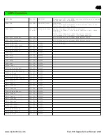
Page 41: ...1 20 2f 32 47 LFO 2 30 3f 48 63 ENV 1 Normal 40 4f 64 79 ENV 1 Inverted 50 5f 80 95 ENV 2 Normal 60 7f 96 127 ENV 2 Inverted DCO LFO Mod Amount 0c 12 00 7f 0 127 DCO LFO Source 0d 13 yy yy 00 3f 0 63...

Page 42: ...5f 88 95 Sync 1 8 Note Triplets 60 67 96 103 Sync 1 16 Note 68 6f 104 111 Sync 1 16 Note Triplets 70 73 112 115 Sync 1 32 Note 74 77 116 119 Sync 1 32 Note Triplets 78 7f 120 127 Sync 1 64 Note Bank...

Page 43: ...PATTERN Enabled 70 7f 112 127 ARP SEQ PATTERN Enabled Hold Pedal 40 64 yy yy 00 3f 0 63 Off 40 7f 64 127 On ENV 2 Attack 41 65 00 7f 0 127 ENV 2 Decay 42 66 00 7f 0 127 ENV 2 Sustain 43 67 00 7f 0 127...

Page 44: ...3 yy yy 00 3f 0 63 Off 40 7f 64 127 On Pattern VCA Level 72 114 yy yy 00 3f 0 63 Off 40 7f 64 127 On Pattern Level 73 115 00 7f 0 127 Program Change 77 119 yy yy 00 7f 0 127 Program Number Note this i...

Page 45: ...PW PWM Mod Amount 0a 10 0 4096 DCO LFO Mod Amount 0c 12 0 4096 DCO ENV Mod Amount 0e 14 0 4096 LFO1 Rate 13 19 0 4096 LFO1 Delay 14 20 0 4096 LFO2 Rate 16 22 0 4096 LFO2 Delay 17 23 0 4096 Sub Level 2...

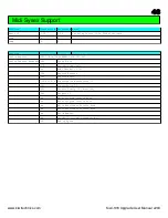
Page 46: ...t 7F Non Rel time reply xx Midi Channel 0 15 06 Enquiry Message 02 Enquiry Reply 00 21 16 Kiwitechnics Manufacture ID 60 Kiwitechnics ID 03 Product Family ID Kiwi 106 00 Product ID xx Major Program Ve...

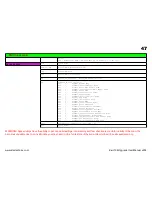
Page 47: ...Patch Name 0c Transmit Receive Patch Name 0d Request Patch Parameter 0e Transmit Receive Patch Parameter 0f Request Global Parameter 10 Transmit Receive Global Parameter 11 Request Pattern Edit Buffer...

Page 48: ...ill not be transmitted even if enabled 05 5 Enable Sysex 0000000x x Off On set On 06 6 Enable Program Change 000000xx xx 00 None 01 PC Receive Enabled Default 02 PC Transmit Enabled 03 PC Receive Tran...

Page 49: ...20 AT Level 0xxxxxxx x Range 00 7f 0 127 15 21 Key Trans Disable 0000000x x Disable Key Transpose 0 enable 1 disable 16 22 Display Mode 000000yz z Clock Display 0 Off 1 On y Scrolling Display 0 Off 1...

Page 50: ...bit command 000xxxxx 0yyyyyyy 0000xxxx xyyyyyyy 19 25 DCO Bend Mod Amount Hi 000xxxxx 1a 26 DCO Bend Mod Amount Lo 0yyyyyyy Hi Lo are combined to make single 12 bit command 000xxxxx 0yyyyyyy 0000xxxx...

Page 51: ...yyy 0000xxxx xyyyyyyy 2b 43 VCF ENV Amount Hi 000xxxxx 2c 44 VCF ENV Amount Lo 0yyyyyyy Hi Lo are combined to make single 12 bit command 000xxxxx 0yyyyyyy 0000xxxx xyyyyyyy 2d 45 VCF Key Amount Hi 000...

Page 52: ...3f 63 Env 2 Sustain Lo 0yyyyyyy Hi Lo are combined to make single 12 bit command 000xxxxx 0yyyyyyy 0000xxxx xyyyyyyy 40 64 Env 2 Release Hi 000xxxxx 41 65 Env 2 Release Lo 0yyyyyyy Hi Lo are combined...

Page 53: ...Step 01011 Sync 8th note triplets 8 Clocks Step 01100 Sync 16th note 6 Clocks Step 01101 Sync 16th note triplets 4 Clocks Step 01110 Sync 32nd note 3 Clocks Step 01111 Sync 32nd note triplets 2 Clocks...

Page 54: ...0 unison only 1 All modes except Mono 5d 93 Arp Control 00yyy0zz zz 00 1Oct 01 2Oct 10 3Oct yyy 000 Up 001 Dn 010 U D 011 Rndm 100 As Played 5e 94 AT Control 00000xyz z DCO LFO 1 on y VCF Cutoff 1 on...

Page 55: ...32nd note 3 Clocks Step 1011 32nd note triplets 2 Clocks Step 1100 64th note triplets 1 Clocks Step Clock source is Master Clock 64 100 Seq Control 000vwxyz z Reserved y KeyDownPlay 0 Seq always play...

Page 56: ...triplets 1 Clocks Step Sync source is Master Clock 68 104 Seq Clock Divide 0000yyyy yyyy 0000 Half Note 48 Clocks Step 0001 Quarter note 24 Clocks Step 0010 8th note 12 Clocks Step 0011 8th note half...

Page 57: ...mit Receive Pattern Dump Pattern Number 29 data bytes Pattern Number 0000xxxx x 0 7 for pattern 1 8 WARNING This command will overwrite the current sounding Pattern with the Pattern selected 00 13 0 1...

Page 58: ...rved 26 bytes Reserved for future expansion 2f 67b 47 1659 Seq Steps 124 x 13 1612 Note 1 0xxxxxxx Note 2 0xxxxxxx Note 3 0xxxxxxx Note 4 0xxxxxxx Note 5 0xxxxxxx Note 6 0xxxxxxx Byte 7 00abcdef Byte...

Page 59: ...gle 12 bit command 000xxxxx 0yyyyyyy 0000xxxx xyyyyyyy 0f 15 Request Global Parameter 0 Data Bytes 00 0 Global Parameter Number 000xxxxx x Data Offset Use Data Position for Parameter Number Data forma...

Page 60: ...Step Sequence step 0xxxxxxx x 0 124 for Sequence step 16 22 Transmit Receive Edit Buffer Seq Step Seq Step 14 data bytes Sequence step 0xxxxxxx x 0 124 for Sequence step Seq Length 0xxxxxxx x 0 No Seq...

Reviews: