


Calibration
54
Keysight M9182A/M9183A Calibration and Verification Procedure
Ohms Calibration (2W and 4W) and DCI Source Gain Procedures
Review
before beginning this procedure.
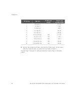
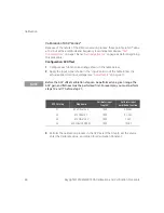
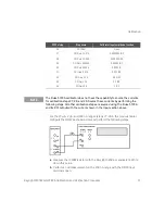
Configuration: Ohms (4-wire and 2-wire as indicated)
This procedure adjusts the gain for both the 4–wire and 2–wire ohm functions,
and the offset compensated
Ω
function. Steps 44 thru 48 are also used to
calibrate the DCI source gain levels.
1
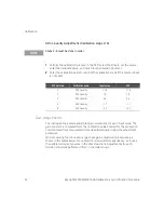
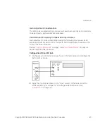
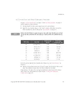
Configure each function and range shown in the table below.
2
Apply the input signal shown in the “Input” column of the table. Enter the
actual applied resistance. When attaching the inputs, note that some of the
inputs are attached using a 2-wire configuration and some are attached in a
4-wire configuration as shown in the table below.
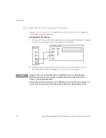
Because of the difficulty in performing this calibration point, the M9183A
automatically uses the 4W
Ω
Gain 20
Ω
calibration value when that test step is
performed. This will not add < 1 m
Ω
to the accuracy. If you choose to calibrate
step 52 to improve the accuracy, the recommendation is to use the Fluke 5720A.
Use Ext. Sense and 2W compensation with stacked BNC connectors at the DUT
input to provide a accurate resistance to the DMM.
NOTE
– Calibration steps 43, 50, 51, and 52 are for M9183A only and are skipped for
the other products.
– The M9183A uses calibration steps 44, 45, 46, 47, 48 to calibrate the DCI
source function ranges 10 mA, 1 mA, 100
μ
A, 10
μ
A, and 1
μ
A respectively.
These steps must be performed to calibrate the Ohms function for the
M9182A.
– Before step 43 can be performed, Step 1 (Zeros) must be performed.
– Before steps 44-48 can be performed, DCI Source 0 (Step 43) and DCV gains
(steps 7-11) must be performed.
– Calibration Step 52 (20
Ω
, 2W Gain) requires special care in performing. Since
this is a 2-wire measurement and the M9183A if a very accurate product, the
exact input resistance provided to the product must be entered as the
calibration value including any lead resistance.


