


Calibration
Keysight M9182A/M9183A Calibration and Verification Procedure
51
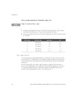
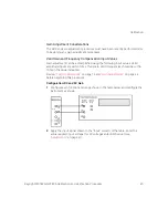
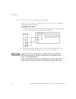
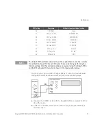
For the 20
μ
A, 2
μ
A, and 200 nA ranges (steps 27-29 in the previous table),
configure the DMM as shown below and perform the following steps.
a
Measure the 10 M
Ω
resistor with the Keysight 3458A or equivalent. Write
down this value.
b
Perform a null measurement on the 200 nA range with the DMM input
terminals open.
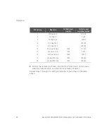
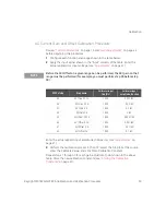
SFP Cal step
Step name
Calibrator input amplitude, function
26
DCI Offset
Open
27
DCI Gain 2E-07A
0.0000002 IDC
28
DCI Gain 2E-06A
0.000002 IDC
29
DCI Gain .00002A
0.00002 IDC
30
DCI Gain .0002A
0.0002 IC
31
DCI Gain .002 A
0.002 IDC
32
DCI Gain .02 A
0.02 IDC
33
DCI Gain .2 A
0.2 IDC
34
DCI Gain 2 A
2 IDC
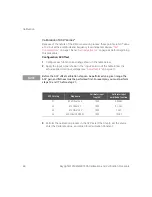
NOTE
The Fluke 5720A calibrator does not have the capability to source the currents
for calibration steps 27, 28, and 29. Source these currents by performing the
following steps. All other calibration steps are sourced using the Fluke 5720A
and its DCI output with the current shown in the Input section above.


