background image

Keysight M8100A Series Arbitrary Waveform Generators Getting Started Guide

31

Basic Setup for M8100A

2


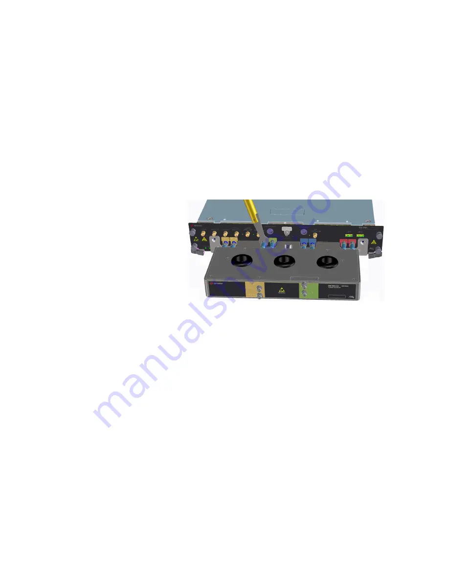
5 Screw torque will be each screw 1.7 Nm.
6 Place the 8x connectors of the M8199A-ILV on the plugs available on 

the M8199A front panel. 

7 Screw the nut of the connector by hand until you are sure that the nut 

runs in the thread.

8 Use the torque wrench (8710-1765) to fix the nut with the right torque 

(0.9 Nm) at all 8 connectors of the M8199A-ILV. The required torque 

for 1.85 mm connectors is 0.9 Nm (8lb-inch).

9 Mount the M8199A instrument together with M8199A-ILV back to the 

AXIe Chassis.

Summary of Contents for M8008A

Page 1: ...Getting Started Guide Keysight M8100A Series Arbitrary Waveform Generators M8199A Arbitrary Waveform Generator M8008A Clock Generator M8158A Arbitrary Waveform Generator Remote Head ...

Page 2: ...ation No additional government requirements beyond those set forth in the EULA shall apply except to the extent that those terms rights or licenses are explicitly required from all providers of commercial computer software pursuant to the FAR and the DFARS and are set forth specifically in writing elsewhere in the EULA Keysight shall be under no obligation to update revise or otherwise modify the ...

Page 3: ...at altitudes of up to 2000 meters Refer to the specifications tables for the ac mains voltage requirements and ambient operating temperature range Before Applying Power Verify that all safety precautions are taken The power cable inlet of the instrument serves as a device to disconnect from the mains in case of hazard The instrument must be positioned so that the operator can easily access the pow...

Page 4: ... secondary packaging indicates compliance to China standard GB 18455 2001 Indicates that antistatic precautions should be taken CSA is the Canadian certification mark to demonstrate compliance with the Safety requirements CE compliance marking to the EU Safety and EMC Directives ISM GRP 1A classification according to the international EMC standard ICES NMB 001 compliance marking to the Canadian EM...

Page 5: ...e affixed label indicates that you must not discard this electrical electronic product in domestic household waste Product Category With reference to the equipment types in WEEE Directive Annex I this product is classed as a Monitoring and Control instrumentation product Do not dispose in domestic household waste To return unwanted products contact your local Keysight office or see http about keys...

Page 6: ...ith USB option The M8100A BU6 system has the M8100A module s and pre configured system pre installed M9537A with M8070B and M8199A module driver consisting of one M9505A 5 slot AXIe chassis with USB option and one M9537A AXIe Embedded PC Controller If you ordered a system that requires on site installation of individual M8100A modules or the M9537A AXIe Embedded Host Computer into the M9505A AXIe ...

Page 7: ...100A Modules 14 M9505A AXIe Chassis 15 AXIe Embedded System Module USB ESM 16 Keysight M9537A AXIe Embedded Controller Module 17 Host Computer 17 M8199A Arbitrary Waveform Generator 18 M8199A Module Components 18 M8199A Front Panel Connectors 19 M8008A Clock Generator 20 M8008A Module Components 20 M8008A Front Panel Connectors 21 M8158A Arbitrary Waveform Generator Remote Head 22 M8158A Remote He...

Page 8: ...ect via PCIe 29 Step 4 Connect the M9505A AXIe Chassis to a Power Supply 29 Step 5 Connect M8199A ILV to the M8199A Instrument 30 Step 6 Connect M8008A Clock Source to M8199A AWG Module 32 Step 7 Power Up if connecting via PCIe 36 Step 8 Verify Basic M8199A Operation 37 Step 9 Install Keysight IO Libraries Suite not required for M8100A BU6 38 Step 10 Install M8070B Software not required for M8100A...

Page 9: ...er Package Interface from M8070B Software 42 Step 15 Enabling Disabling the Interleaving Mode 43 Step 16 Turning off the Chassis and Modules If Required 44 3 Maintenance Locating Electronic Manuals and Online Help 46 Routine Care 46 Updating Software Components 47 Contacting Keysight Service and Support 47 Index ...

Page 10: ......

Page 11: ...or 20 M8158A Arbitrary Waveform Generator Remote Head 22 This chapter introduces you to Keysight s M8100A Series Arbitrary Waveform Generators It also introduces you to the concept of using a host computer to communicate with the M8100A The M8100A supports the following modules M8199A Arbitrary Waveform Generator M8008A Clock Generator M8158A Arbitrary Waveform Generator Remote Head ...

Page 12: ...minal analog bandwidth Provides research engineers a high performance signal source for arbitrary signals enabling development of designs up to 140 GBaud Keysight s M8199A 256 GSa s AWG delivers twice the sampling rate of any AWG on the market today coupled with at least 50 percent higher analog bandwidth As a result research engineers can quickly develop advanced components for terabit transmissi...

Page 13: ... Interleaving can boost the sample rate to 256 GSa s enabling symbol rates beyond 128 GBaud Wideband RF Signal Generation in Wireless and Aerospace Defense applications Latest developments in radar and wireless technologies require signals with modulation bandwidths beyond 10 GHz in some cases up to 30 GHz with good signal quality Generating those signals on an IF rather than I Q is another import...

Page 14: ... a license for that option The M8100A supports the following modules M8199A Arbitrary Waveform Generator M8008A Clock Generator M8158A Arbitrary Waveform Generator Remote Head The M8199A module occupies two slots of the 5 slot M9505A AXIe chassis It must be installed in slots 1 through 2 in the AXIe chassis unless the M9537A AXIe Embedded Controller is installed The M9537A AXIe Embedded Controller...

Page 15: ...se instrument modules the M9505A AXIe chassis also provides power a cooling system a PCIe Gen2 local data bus a Gigabit LAN interconnect and a USB and PCIe connection for external host computer connectivity Refer to the Keysight M9505A AXIe Chassis Startup Guide to get detailed information about the AXIe chassis Figure 2 M9505A 5 slot chassis NOTE The USB connection is recommended when using a lap...

Page 16: ... modules and manages power requirements monitors chassis temperature and controls variable speed chassis fans monitors module sensors and reports component failures to a system log acts as a Gigabit Ethernet switch forwards frames along the backplane connects an external host computer to the chassis synchronizes timing across all modules through the Keysight Trigger Bus using an internal or extern...

Page 17: ...llowing figure displays this module Figure 4 M9537A AXIe Embedded Controller Module Host Computer A host computer is used to host all the software components of the instrument modules needed to control configure and use the modules communicate with the ESM of the M9505A AXIe chassis to allow you to monitor and control the chassis A host computer can be the M9537A AXIe Embedded Controller module a ...

Page 18: ...generation of up to 140 Gbaud with outstanding signal quality in a 2 slot AXIe module Whether testing the discrete components of optical coherent systems or path finding for terabit transmission in the next generation data center the M8199A is ideal for addressing the need for high sample rates and high analog bandwidth The M8199A is an instrument module that can be installed into the M9505A 5 slo...

Page 19: ...ing a grounded wrist strap to minimize the possibility of electrostatic damage Connector Description Remote Head 1 2 Remote Head Control This output provides power and control signals for the remote head amplifier Data Out and Data Out Data outputs 1 85 mm Sync In Out A B The Sync In OUT usage depends on whether the M8199A is connected to the M8008A clock module or whether it is driven by an exter...

Page 20: ...is an instrument module that can be installed into the M9505A 5 slot AXIe chassis It comes as a 1 slot AXIe module which allows the M8008A plus up to two M8199A AWG modules to be plugged into a single 5 slot AXIe chassis The M8008A Clock Generator module provides the following key features 32 64 GHz continuous frequency range Output amplitude up to 10 dBm Very low intrinsic jitter and wideband pha...

Page 21: ...ons such as wearing a grounded wrist strap to minimize the possibility of electrostatic damage Connector Description Sync In Reserved for future use Sync Out A B C D This output is used to synchronize two or more M8199A modules to a common system clock It is connected to the Sync In of the M8199A module Sample Clk Out 1 and Sample Clk Out 2 Sample clock outputs connected to Sample Clk In on up to ...

Page 22: ...es which are fixed on the back side of M8158A These cables need to be connected to M8199A Remote Head and the DataOut ports of M8199A ILV Passive Combiner M8158A Remote Head Components The following figure displays the front panel of the M8158A remote head with its various components Figure 7 M8158A remote head As displayed in Figure 7 on page 22 the M8158A remote head has the following components...

Page 23: ...ith each channel of M8199A remote head ports The length of these cables are 760 mm Ensure that the chassis is NOT powered up or connected to a power source while making connections to M8158A Also make sure NOT to remove the M8158A connections when it is powered on However if you wish to remove the M8158A connections ensure that the instrument is powered off ...

Page 24: ......

Page 25: ...ock Source to M8199A AWG Module 32 Step 7 Power Up if connecting via PCIe 36 Step 8 Verify Basic M8199A Operation 37 Step 9 Install Keysight IO Libraries Suite not required for M8100A BU6 38 Step 10 Install M8070B Software not required for M8100A BU6 38 Step 11 Starting the M8070B Software 39 Step 12 Install Module Driver Package in the M8070B Software 39 Step 13 Install the Licenses 40 Step 14 St...

Page 26: ...Embedded PC and M8100A BU6 is AXIe Chassis with Embedded PC Accessories The accessories will vary depending on the M8100A and the options that you ordered while purchasing the module Accessories include standard items that are shipped with the M8100A as well as optional items that you ordered separately Please check the M8100A product data sheet for the latest list of default and optional accessor...

Page 27: ...ight Sales Office If you need assistance finding Keysight contact information go to www keysight com find assist worldwide contact information for repair and service Step 2 Set up the M8100A This step does not have to be performed while verifying the basic setup for power up and connectivity However you will need to decide on a benchtop or rack mounted usage of the M8100A after this basic verifica...

Page 28: ... USB 2 0 Mini B recommended PCIe 2 0 8x only for highest data throughput and desktop PC VGA resolution 1024 x 768 1 5 GB or more free hard disc space Software requirements Windows 10 64 bit operating system Keysight I O libraries version 17 1 To connect via USB If you are planning to use USB connectivity between the M9505A AXIe Chassis and host computer then you can use a laptop or desktop compute...

Page 29: ...t M9505A AXIe Chassis Figure 9 PCIe port on the front panel of the AXIe ESM Step 4 Connect the M9505A AXIe Chassis to a Power Supply You can use an external power supply typically AC power mains 1 The instrument module uses the power supplied by the M9505A AXIe Chassis in which it is installed The M9505A AXIe Chassis power cord comes with the chassis shipment Insert the power cord into the inlet a...

Page 30: ...steps to connect M8199A ILV assembly to M8199A instrument 1 Remove M8199A instrument from the AXIe Chassis 2 Place M8199A instrument and M8199A ILV on a flat surface for example on a desk 3 Move M8199A ILV to the front panel of the M8199A instrument as in the following figure 4 Fix it with 2x screw 0515 2741 and a long screw driver Torx T20 or with screw driver 8710 2904 ...

Page 31: ...he plugs available on the M8199A front panel 7 Screw the nut of the connector by hand until you are sure that the nut runs in the thread 8 Use the torque wrench 8710 1765 to fix the nut with the right torque 0 9 Nm at all 8 connectors of the M8199A ILV The required torque for 1 85 mm connectors is 0 9 Nm 8lb inch 9 Mount the M8199A instrument together with M8199A ILV back to the AXIe Chassis ...

Page 32: ...ule In this case make the connections as described below 1 Connect the 45 cm 1 85 mm blue clock cable M8199 61624 from Sample Clk Out of M8008A to Clk In of M8199A 2 Connect the M8199A 811 sync cable M8199 61620 from Sync Out of M8008A to Sync In of M8199A Figure 11 on page 32 shows how to connect the M8008A clock generator module to the M8199A AWG module Figure 11 Connecting M8008A clock generato...

Page 33: ...A The output power needs to be set at the PSG for various sample clock frequencies The output power level should start at 7dBm at 50 GHz and should be increased linearly to 11 dBm at 60 GHz This means as we increase the frequency from 50 GHz to 60 GHz there is a linear increase in the output power from 7 dBm to 11 dBm Above 60 GHz a power level of 11 dBm should be used The following table shows th...

Page 34: ...85 m m 450mm Make the connections as described below 1 Connect the M8008A Clock Generator Sync Out port with both the M8199A AWG Sync In ports using the sync cable blue cable 2 Connect the M8008A Clock Generator Sample Clock Out port with both the M8199A AWG Clock In ports using clock cable red cable Figure 12 on page 34 shows how to connect M8008A clock generator module to the two M8199A AWG modu...

Page 35: ...M8199 61624 MWX261 1 85 1 85 m m 450mm Make the connections as described below 1 Connect the M8008A Clock Generator Sync Out port with all the four M8199A AWG Sync In ports using sync cable blue cable 2 Connect the M8008A Clock Generator Sample Clock Out port with all the four M8199A AWG Clock In ports using clock cable red cable Figure 13 on page 35 shows how to connect M8008A clock generator mod...

Page 36: ... the host computer 3 Wait until the Access LED s of the module s in the chassis is are solid green 4 Power up the host computer By this time the Status LED of the ESM in the chassis and the Access LED s of the module s should have been steady green indicating a power ready status of the setup The step to power up the host computer is not required if you are using the M9537A AXIe Embedded Controlle...

Page 37: ...ght or powers up to a steady red light the chassis has detected a failure and requires service If the Fail LED on the front panel of the instrument module is steady red and does not turn off it indicates a power fault condition In such a situation the instrument module may require repair service NOTE If you plan to connect the M8100A to a corporate LAN and the M9537A AXIe Embedded Controller is in...

Page 38: ... as prompted during the installation 5 After installation you will see the Keysight IO icon in the taskbar notification area of the host computer screen Step 10 Install M8070B Software not required for M8100A BU6 The M8070B software does not require any license for its installation However it can only be used to perform some basic operations For advance operations you need to install the driver pa...

Page 39: ...Keysight M8070B Keysight M8070B to verify software installation Step 11 Starting the M8070B Software 1 Ensure that the system is powered up and ready to start as described in the sections Basic Setup for M8100A on page 25 2 On the host computer click on Start All Programs Keysight M8070B Keysight M8070B 3 Select the module options from M8070B Startup Options dialog box For details on the M8070B St...

Page 40: ...ote programming refer to the M8000 Series Programming Guide Step 13 Install the Licenses The usage of M8070B plugins is govern by Keysight Licensing Keysight Licensing provides tools and processes for floating USB portable node locked and transportable licenses These licenses can be installed using the Keysight License Manager It helps you install licenses on your local machine instrument or compu...

Page 41: ...re are started the license is recognized by the M8070B software and compared to the module s serial number If the PC Host ID and serial number match the EEPROM in the module is programmed and the option is enabled Even if the M8070B software license is transported to another host computer the module option will remain enabled The following procedure shows how to redeem and install a module license...

Page 42: ... example M8199A from the M8070B Startup Options dialog box For details on the M8070B Startup Options dialog box refer to M8000 Series User Guide or Online Help 3 Click OK The M8070B software screen should now be displayed as shown in the following figure For details on the how to control the driver package using M8070B software interface refer to M8000 Series User Guide or Online Help For informat...

Page 43: ...nected even though no combiner serial no is registered The connection of a remote head is only checked at startup To enable the ILV do the following 1 Go to Parameters Interleaving Combiner S N 2 Enter the serial no of the ILV option Combiner into the Combiner S N text field 3 Restart the M8070B application After the restart the ILV mode will be enabled To disable the ILV do the following 1 Go to ...

Page 44: ...sequence 1 Turn off the host computer If you are using the Keysight AXIe Embedded Controller module as the host computer ensure that you shut down the controller by executing the Windows shutdown process 2 Turn off the chassis by pressing the chassis ON STANDBY switch on the front panel of chassis Do not use the circuit breaker for routine turn off The module s are turned off automatically with th...

Page 45: ...00A Series Arbitrary Waveform Generators Getting Started Guide 3 Maintenance Locating Electronic Manuals and Online Help 46 Routine Care 46 Updating Software Components 47 Contacting Keysight Service and Support 47 ...

Page 46: ... initial chassis verification or troubleshooting do not operate the chassis with empty slots Always insert a filler panel in empty slots This is especially important for the slots on either side of an installed instrument module This allows proper air flow and cooling and provides EMI shielding for the chassis and installed components Leaving slots empty can increase fan speed raise ambient noise ...

Page 47: ...nd click Find Model number is located on the front panel of the module 5 Click the Driver and Software link on the module page 6 Download the required software update from the list of available updates Contacting Keysight Service and Support To locate a sales or a service office near you go to www keysight com find contactus CAUTION The enclosure surface of the module may become hot during use If ...

Page 48: ......

Page 49: ...19 21 Interleaved 43 Interleaving Mode 43 IO Libraries install 38 L LAN connection 16 LEDs Access 18 20 Fail 18 20 M M1800A Series Arbitrary Waveform Generators 11 M8008A Clock Generator 11 M8070B Software 39 M8070B Software install 39 M8070B Software starting 39 M8100A 14 M8158A 11 14 M8158A Components 22 M8158A Remote Head Components 22 M8199A 11 14 M8199A Module Components 18 20 M9505A 15 M9505...

Page 50: ...This information is subject to change without notice Keysight Technologies 2022 Edition 2 1 March 2022 Printed in Germany www keysight com ...

Reviews: