Connecting to a KIT200
home thereafter
s
y
s
tem
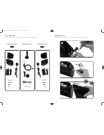
i) Remove the transmitter speaker cable adaptor.
ii) Cut the rear left and rear right KIT200 speaker cables.
iii) Screw in the rear left and the rear right speaker cables to the adaptor.
LED indicator
Connecting the Tran
s
mitter Unit
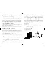
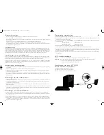
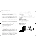
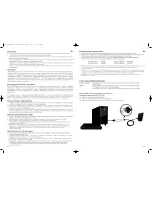
i) Power OFF all the A/V equipment during the installation of wireless system.
ii) Connect the supplied AC-DC adaptor to the DC Jack on the rear panel of the transmitter unit. Connect the KEF
Audio Jack connector to the key hole socket on the rear panel of the transmitter unit .
iii) Connect the speaker inputs to the REAR LEFT speaker and REAR RIGHT speaker terminals of your AV receiver using
the provided cable.
iv) Rotate the position of the transmitter unit such that the front panel is facing toward the wireless speakers.
v) Connect the power supply to the mains socket. Turn on the transmitter by pressing the power button on the front
panel.
vi) Ensure the blue bonding light is permanently on, this shows that the transmitter unit and receiver units are successfully
bonded and ready to output the audio. If the bonding light is flashing, then check that both receiver units have been
powered-on and are within range.
vii) Turn on the audio source which is connected to the transmitter unit and adjust the volume level accordingly from the
remote control of the audio source.
10
9
EN
Rear Left + White
Rear Right + Red
Rear Left - Black
Rear Right -
Blue
Steady:
Transmitter and receiver units are successfully bonded and ready to output audio.
Flashing:
Module is powered on but there is a problem that will prevent audio from sounding.
1) Check that all modules are powered on.
2) Check that both receivers are within range.
EN
SL+
SL-
SR+
SR-
Connecting the Reciever Unit
s
A
ss
embly to the Floor
s
tand
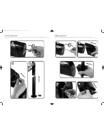
i) Remove the speaker terminal caps from your HTS5001.2 speakers, place the supplied contact pin holder on the
terminal posts and then replace the terminal caps.
ii) Insert the supplied long bolt into each of the KHT5001.2 speaker foot screw hole.
iii) Slide the top of wireless receiver unit over the long bolt and then push down ensuring that the terminal contacts align
with the wireless module socket.
iv) The wireless receiver units have been pre-set for either LEFT audio channel or RIGHT audio channel. Refer to the
small marking on the rear of the wireless receiver units to ensure that the correct receiver unit is used for left or
right speaker.
i) Insert the bolt provided into the bottom of the wireless receiver units to secure the wireless module to the speaker
and tighten.
ii) Insert the AC-DC adaptor cable through the base of the floor stand such that the plug can be connected to the
DC Jack connector of wireless receiver unit.
iii) Assemble the complete wireless receiver unit by aligning the rear and then the front guides and pressing it down into
the KHT5001.2 floor stand,
iv) Connect the AC-DC adaptor plug into the main AC socket. The wireless receiver units will power-on and the blue
bonding light on the front of the wireless module will be flashing to show that the speaker is now ready to output
audio when the transmitter is turned on.
A
ss
embly to the De
s
ktop
s
tand
i) Place the wireless receiver unit into the aluminium casing and screw the extension bolt to the bottom of the
aluminium casing.
ii) Assemble the metal foot to the casing and align the hole to the bolt accordingly.Tighten the bolt with the nut provided
at the bottom of the metal foot.
iii) Plug the AC-DC adaptor to the DC Jack connector of wireless receiver unit from the hole provided underneath the
aluminium casing.
iv) Connect the AC-DC adaptor plug into the main AC wall socket.The wireless receiver units will power-on and the blue
bonding light on the front of the wireless module will be flashing to show that the speaker is now ready to output
audio when the transmitter is turned on.
Introduction
Surround
s
ound
s
etting
s
This wireless system is intended for use as part of a home entertainment surround sound speaker system as left surround
speaker and right surround speaker. The KEF Wireless system implements unique RF transmission technology based on
AAFHSS (Advanced Adaptive Frequency Hopping Spread Spectrum).This ensures exceptionally robust delivery of the high
quality audio channels that are encoded using HFADPCM (High Fidelity Adaptive Differential Pulse Code Modulation).
It can be assembled with the KHT5005.2 rear speakers either with the floor stand or the desk top foot. It is for indoor
use only.
Ensure that your AV receiver is set to 5.1 channel surround sound. If it has a calibration feature then this can be used to
independently adjust the rear speaker volume levels to compensate for your room. If there is an adjustable bass
management setting ensure that it is set to “small speakers” or with a crossover of approximately 100Hz.
The wireless system is specifically designed for audio and does not require any set up. The correct receiver is required
for the LEFT rear speaker and the RIGHT rear speaker. Simply assemble the wireless module into the speaker stand,
plug it into the mains and switch them on.
K7243_KEF Wireless 5000 series Multi-lang 13/3/07 16:19 Page 11

