background image

GB 26

GB

With this type of setpoint selection it is permissible to set several
inputs at the same time. The table below shows which travelling
speeds are used.

Symbole:

1 =

Input is set at  24 V

0 =

Input may not be set

X =

Setting has no effect

Function of the digital setpoint inputs

X3.2

X3.3

X3.4

V = 0

0

0

0

VB

1

0

0

VE

0

1

0

VN

1

1

0

VI

0

0

1

V1

1

0

1

V2

0

1

1

V = 0

1

1

1

b)

Input coded
setpoint  selection
LF.02 = 2

8. Parameter 

Description

The analog setpoint selection is set with the terminals
 X2.14 / X2.15.

0 ... ±10V  =  0 ... ±max. system speed (LF.20)

Terminal X3.6 is used to activate/deactivate the starting
routine. The directions below must be followed in the exact
sequence they are listed:
Start: 1.) Terminal X3.6 = 1 

(activate starting routine/open break

)

2.) Preset analog setpoint

Stop: 1.) Remove analog setpoint

2.) Terminal X3.6 = 0 

(close brake)

c)

Analog setpoint selection
LF.02 = 3 or 4

X3.2

X3.3

X3.4

X3.5

X3.6

X3.7

X3.8

V = 0

0

0

0

0

0

0

0

VB

1

X

X

X

X

X

X

VE

0

1

0

0

0

0

0

VN

0

X

1

0

0

0

0

VI

0

X

X

1

0

0

0

V1

0

X

X

X

1

0

0

V2

0

X

X

X

X

1

0

V=0

0

X

X

X

X

X

1

First all three inputs should be set and then the non-
needed inputs should be reset to avoid a wrong speed
selection during a speed change.

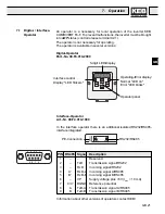
Summary of Contents for COMBIVERT F4-F

Page 1: ...10 98 00 F4 L1B K140 KEB COMBIVERT F4 F Lift Aufzugstechnik Version 1 4 Lift Servo Lift Technology BETRIEBSANLEITUNG INSTRUCTION MANUAL ANTRIEBSTECHNIK...

Page 2: ...f llt insbesondere die Kenntnis und Beachtung der Sicherheits und Warnhinweise Lesen Sie des halb unbedingt die Technische Dokumentation Teil 1 Information Help Tip Danger Warning Caution Attention ob...

Page 3: ...rating Frequency 16 5 2 Digital Output X3 14 Operating FrequencyWarning 16 6 Connection 17 6 1 Wiring Diagram ControlTerminal X2 and I O Expander X3 17 6 2 Connection X4 Incremental Encoder 18 6 2 1 C...

Page 4: ...interference pulses Paired twistedcablesprotectagainstinductiveparasiticvoltages shieldingprovidesprotectionagainstcapacitiveparasiticvoltages Optimal protection is achieved with twisted and shielded...

Page 5: ...mary 9 pole sub D socket parameter interface Operator only optional see page E 21 X4 15 pole sub D socket connection incremental encoder X5 9 pole sub D socket incremental encoder simulation X2 termin...

Page 6: ...1 Ground for X2 10 and digital inputs outputs terminal X2 23 then UX2 10 UX2 23 12 10 V reference voltage 10V 3 max 6 mA 13 Ground for analog inputs outputs 14 Differential voltage input resolution 12...

Page 7: ...speed 2 V2 set value selection see page GB 24 GB 25 8 Option do not connect 9 24 V external voltage input External supply voltage 10 for relay outputs on terminal X3 11 Ground for X3 9 X3 10 12 13 Sig...

Page 8: ...peed has a positive display Whether the cabin moves up or down depends on the phase sequence of the motor wiring and how the hoist is set up in the machine room Note If the entries for forward X2 3 an...

Page 9: ...e command is entered If the input is not set the display S Co Error contactor open appears in parameter LF 98 The power modules are blocked The contactor control can be simulated by bridging input X3...

Page 10: ...ctor The output signal corresponds to the inverted signal of terminal X3 20 Control When the function of the contactor control is not used input X3 1 must be inverted bridged with output X2 9 to simul...

Page 11: ...w This function only works when the incremental encoder is connected and the speed controller is switched on LF 30 0 X3 20 Main Contactor The ouput emits signals that are applied to terminal X3 21 The...

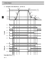
Page 12: ...X3 15 X3 18 X3 4 X3 1 X2 1 v LF 62 LF 63 LF 60 LF 50 LF 51 LF 50 LF 42 LF 61 LF 52 LF 53 LF 52 LF 54 LF 53 LF 54 LF 41 1 2 3 4 5 6 7 8 9 10 11 12 13 4 1 Activation of the Main Drive LF 02 2 Inputs Ou...

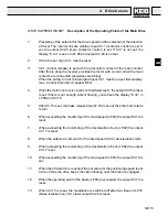
Page 13: ...X3 15 brake is set If there is not enough current flowing you will see the display E nC in LF 98 and X3 15 5 After X3 15 is set the brake release time LF 70 runs out then the motor starts to turn 6 W...

Page 14: ...d DEC ramps of the door drive the values of parameters LF 50 LF 51 LF 53 und LF 54 are valid like with the main drive The set speed rpm for the door drive is preset in parameter LF 46 set speed door d...

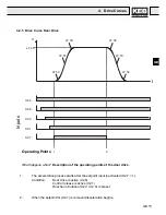
Page 15: ...scription of the operating points of the door drive 1 The acceleration process starts after the setpoint input is activated X2 7 1 Condition Door drive is active X2 6 Control release is active X2 1 Di...

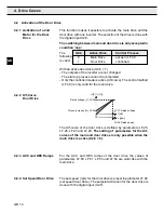
Page 16: ...IVERT F4 F Lift from overheating during 16kHz operation and thus prevent the lift from being interrupted the operating frequency can be reduced dependent on the heat sink temperature only in condition...

Page 17: ...VN Setpoint selection only with LF 2 2 Supply With binary coded setpoint selection LF 2 1 terminal assignment see page GB 25 GB 26 X2 9 X2 1 X2 2 X2 3 X2 4 X2 5 X2 6 X2 7 X3 1 X3 2 X3 3 X3 4 X3 5 X3...

Page 18: ...when the inverter and voltage supply are shut off Encoder Specification 1 Voltage Supply 5 V 10 max 110 mA 2 Increments 256 10000 inc recommended 2500 inc Observe limit frequency of encoder increments...

Page 19: ...als Rectangular pulse signal Two square wave pulses that are electrically by 90 out of phase and their inverse signals 2 5 V 0 V U0 0 5 V 20 U0 0 5 V 20 U0 approx 2 5 V 6 Connection PIN No Signal PIN...

Page 20: ...connected disconnected when the inverter and voltage supply are shut off PIN Nr Signal PIN No Signal 1 9 COS 2 10 SIN_REF 3 SIN_LO 11 4 COS_LO 12 5 SIN_REF_LO 13 6 14 7 15 8 SIN Housing Shield 6 2 3 C...

Page 21: ...rating Errordisplay Normal LED on Error LED blinks 5 digit LED Display Interface control Display LED flickers RS232 RS485 PE Connection Interface Operator Art Nr 00 F4 010 1009 In the interface operat...

Page 22: ...blinking point determines the active changeable part of the parameter identification Display Parameter Group Display Parameter Number 7 3 Parameter Selection change between parameter group and parame...

Page 23: ...In 0 In 57 ENTER Parameters are programmable parameters whosechangesarefirstaccepted and stored after the ENTER key is pressed LF 0 LF 2 LF 4 LF 18 LF 19 LF 30 LF 69 Parameter Groups LF Parameter LF...

Page 24: ...message see p GB 44 GB 45 Error Malfunction or If a malfunction occurs during operation the actual display is overwritten with the error message By pressing the keys UP or DOWN the error message is re...

Page 25: ...This parameter can only be used when a valid password is entered in parameter LF 0 Value range 0 399 400 401 9999 Factory setting 440 8 1 LF Parameter Steering Operating Mode The value 400 may not be...

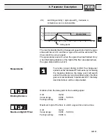
Page 26: ...ls X2 14 X2 15 0 10V 0 max system speed LF 20 Terminal X3 6 is used to activate deactivate the starting routine The directions below must be followed in the exact sequence they are listed Start 1 Term...

Page 27: ...rameter for the selected motor and does independently a Power On Reset Unit 1 Value range 0 ASM 1 SSM Factory setting 0 ASM Adjustment value in accordance with type of the motor With LF 5 travel direc...

Page 28: ...speed e g 1500rpmfora4polemotor Askthemanufacturer for the motor rated speed if you cannot find it on the name plate Unit volt Value range 1 650 V Factory setting 400 V Adjustment value in accordance...

Page 29: ...oder can be changed by software with the parameter LF 18 Unit 1 Value range off on Factory setting off Adjustment value dependent on rotating field See also page GB 57 Start Up Assistance ASM Encoder...

Page 30: ...ing 1 Adjustment value in accordance with the system data Catenary Suspension Unit percent of the rated torque Value range 0 0 25 5 Factory setting 6 0 Door drive see pages GB 14 D 15 Torque Increase...

Page 31: ...stment value 0 open loop operation 1 select via terminal X2 5 2 closed loop operation with speed feedback 3 closed loop operation with speed feedback and precontrol torque With open loop operation LF...

Page 32: ...ory setting 2 x LF 91 Adjustment value approx 2 x LF 91 dependent on load and the motor connected ASM Maximum Torque Boast Adjusts the u f curve only during open loop operation LF 30 0 Unit of input v...

Page 33: ...Adjusted value as needed 8 Parameter Description Set Value VB Correction Speed Unit meter per second Value range 0 000 LF 20 Factory setting 0 000 m s Adjusted value like LF 20 or smaller Unit meter...

Page 34: ...tly depending on their age physical and mental state and whether they awaited this movement or not Empirical values 0 5 0 8m s3 for retirement homes hospitals apartment buildings 0 8 1 2m s3 for offic...

Page 35: ...to comfort When the deceleration jerk is set too low parameter LF 53 is no longer valid Deceleration Unit meter per second2 Value range 0 10 2 00m s2 Factory setting 0 90 m s2 Adjusted value according...

Page 36: ...dOH Error motor overheating The malfunction can be reset when the motor has cooled down and the frequency inverter shows the display E nOH Error no overheating If the motor cools down before the delay...

Page 37: ...the cabin is empty rated torque 5 V cabin weight half load counter weight 0 10 V the cabin is full rated torque If the rated torque is too small or too large it can be increased or decreased with LF...

Page 38: ...Speed VE Unit centimeter Value range 0 0 200 0cm Factory setting 0 0 cm Function see parameter LF 71 Unit millimeter Value range 0 300 mm Factory setting 0 mm The levelling position can be exactly ad...

Page 39: ...delay point LF 75 off If the ogive function is switched on and according to the adjusted parameters LF 77 and LF 78 the drive accelerates to the braking distance calculated ogive speed and decelerate...

Page 40: ...tching velocity is too small Ogive Status Special Cases t delay point V VN VE VS If the switching velocity crawl speed the drive accelerates to the crawl speed The ogive status is constantly 0 because...

Page 41: ...the floor are adjusted new the ogive status will be set at 0 Measurements Distance from the delay point to the levelling signal Unit meter Value range 0 000 5 000 m Factory setting 0 000 m Braking Di...

Page 42: ...tion of travel reverse X2 4 I1 16 control mode X2 5 I2 32 drive active X2 6 I3 64 door drive setpoint input X2 7 Example Inputcontrolrelease X2 1 directionandtravelup X2 3 and external error X2 5 are...

Page 43: ...braking control X3 15 X3 16 O8 8 Signal operatingfrequencywarning X3 14 O9 16 Signal delay control X3 17 O10 32 Relay contact crawl speed X3 18 X3 19 O12 128 Relay contact main contactor control X3 20...

Page 44: ...n control release is cleared Facc 64 forward acceleration Fcon 66 forward constant running FdEc 65 forward deceleration nOP 0 no Operation terminal X2 1 is not set LS 70 low speed control release is s...

Page 45: ...load shunt fault E OC 4 Error overcurrent overcurrent short time peak overloading E OH 8 Error overheated overheating of the inverter E OH2 30 Error overheat 2 electronic motor protection E nOH 36 Er...

Page 46: ...in accordance with the motor name plate Unit hertz Value range 10 600 hz Factory setting 200 hz Adjusted value in accordance with the motor name plate Unit ampere Value range 0 1 40 0 A Factory settin...

Page 47: ...the encoder to the rotor position of the motor see also LF b5 The position trimming descriped in parameter LF b5 must not be done if the system position of the motor and encoder is known The position...

Page 48: ...ertotherotorpositionofthemotor must be known By input of 1 into LF b5 the system position trimming will start The drive may not be loaded The ropes must be picked off from the sheave The trimming make...

Page 49: ...load transfer at high efficiency gears Unit 1 Value range 0 65535 Factory setting 0 Adjusted value dependent on ratio of inverter motor and the type of the gear SSM KI Speed Offset Unit newtonmeter Va...

Page 50: ...inverter is switched off The actual operating condition of the inverter can be read in these parameters Theparametersinthisgroupare read only Exception parameters ru 8 ru 12 and ru 25 can be reset wit...

Page 51: ...tion 1V Active Current Actual DC Voltage Peak DC Voltage 8 Parameter Description Terminal X2 upper terminal You can control whether the input signal reaches the inverter control with ru 14 Every input...

Page 52: ...to prevent OL from occuring load reduction on time The OL error is triggered whentheOLcounterreaches100 Thecounterisshownwitha1 resolution Peak Apparent Current Maximummotorcurrentthatoccursduringope...

Page 53: ...ter Description Power On Counter Modulation On Counter Shows the time that the inverter was supplied with power Resolution 1 hour Shows how long the inverter was active Resolution 1 hour modulation ac...

Page 54: ...1CDA 13 F4 FXG 200V 16 kHz Value of the display hex 5 1 4 1 3 1 2 1 1 1 0 1 9 8 7 6 5 4 3 2 1 0 0 t i B s s a l c e g a t l o V V 0 0 2 0 V 0 0 4 1 5 1 t i B t i n u e h t f o e z i S 8 6 t i B e p y...

Page 55: ...ow Customer Number HIGH Displays the customer number Customer Number LOW Displays the customer number Last Error Displays the last error that occurred see LF 99 Shows the total number of errors that o...

Page 56: ...eparable incremental encoder output 7 direct incremental encoder output Software Date DSP Displays the software date The day month and year but only the last digit of the year are shown Example Displa...

Page 57: ...or do as follows 9 1 Inital Start Up Start Parameterize inverter LF parameter Parameter LF 30 2 closed loop operation Preset drive command with return control NO YES YES NO Is direction of travel corr...

Page 58: ...meterizeinverter LF Parameter Start system trimming LF b5 1 Preset drive command with return control E Enc YES Is direction of travel correct for cabin Improvements in drive comfort Exchangemotor phas...

Page 59: ...a must be adjusted on site for the system If the lift does not reach the rated speed during no load downward drive display LF 90 do the following 1 Decrease field weakening speed LF 16 to approx 2 3 o...

Page 60: ...a servo motor LF A0 LF C5 Reverse Direction of travel LF 05 Regulated operation with precontrol torque LF 67 LF 69 Better ogive function Display of the positioning drive LF 92 Error display E OL2 at...

Page 61: ...e Door Drive 351B 1 20 100 50 Hz LF 28 Rated Voltage of the Door Drive 351C 1 1 650 400 V LF 30 Control Method 351D E 1 0 3 0 LF 31 ASM KP Speed 351E 1 1 65535 3000 LF 32 ASM KI Speed 3520 1 1 65535 1...

Page 62: ...LF 89 Actual Speed 3559 R 0 5 rpm LF 90 Actual Lft Speed 355A R 0 001 m s LF 91 ASM Rated Motor Torque 355B R 0 1 Nm LF 92 Positioning Drive 355C R 0 1 cm LF 98 Error State 3562 R Table LF 99 Inverte...

Page 63: ...rent Current 2019 R 0 1 A ru 29 Heat Sink Temperature 201D R 1 C ru 31 Power On Counter 201F R 1 h ru 32 Modulation On Counter 2020 R 1 h In 00 Inverter Type Display 2C00 Table In 01 Rated Inverter Cu...

Page 64: ...LF 41 m s LF 42 m s LF 43 m s LF 44 m s LF 45 m s LF 46 rpm Size Customer adjustment Unit LF 50 m s 3 LF 51 m s 2 LF 52 m s 3 LF 53 m s 2 LF 54 m s 3 LF 60 m s LF 61 m s LF 62 m s LF 63 m s LF 64 V LF...

Page 65: ...ANTRIEBSTECHNIK...
Page 66: ...oci t Fran aise KEB Z I de la Croix St Nicolas 14 rue Gustave Eiffel F 94510 LA QUEUE EN BRIE T l 0033 1 49620101 FAX 0033 1 45767495 E mail sfkeb 4 wanadoo fr KEB UK Ltd 6 Chieftain Buisiness Park Mo...

Reviews: