


81
Part 4 - Diagnosis and T
roubleshooting
N
P
Step 2: Check rectifier wiring circuit
▪ If the wires are loose, fasten the wires. If the wires are OK, replace the main PCB.
Figure 4-4.8: Rectifier and AC filter board in electric control box
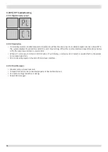
4.13.8 xL2 troubleshooting
Step 1: Check inverter module
▪ Check the DC voltage between terminals P and N. The normal value is 537-586V (power supply voltage specification:
380~415V 3N~), if the voltage is higher than 800V, go to Step 2.
Figure 4-4.9: Inverter module terminals
Step 2: Check inverter module
▪ Check the voltage between terminals P and N on the capacitor board. The normal value is 537-586V (power supply
voltage specification:380~415V 3N~). If the voltage is not in the normal range, there is a problem with the electrolytic
capacitor power supply. Check the power supply for high or unstable voltage. If the power supply voltage value is
normal, then the main PCB has malfunctioned and needs to be replaced.
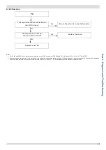
Check AC filter
board wiring
Check drive board input wiring


