


24
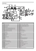
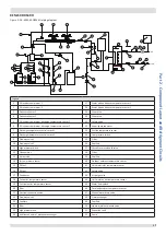
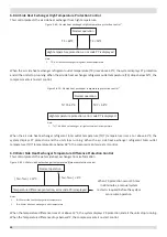
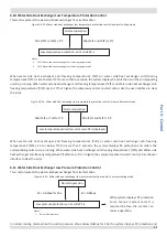
1 General Control Scheme Flowchart
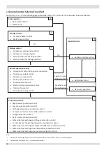
Sections 3-2 to 3-7 on the following pages detail when each of the controls in the flowchart below is activated.
2
7
3
4
5
6
Stop operation
■
Abnormal shutdown
■
System stops
Special control
Standby control
■
Crankcase heater control
■
Water pump control
Startup control
■
Compressor startup delay control
■
Compressor startup program
■
Startup control for heating operation
■
Startup control for cooling operation
Normal operation control
■
Component control during normal operation
■
Compressor output control
■
Compressor step control
■
Water pump select control
■
Four-way valve control
■
Electronic expansion valve control
■
Outdoor fan control
■
Spray liquid cooling control
Protection control
■
High pressure protection control
■
Low pressure protection control
■
Discharge temperature protection control
■
Compressor and inverter module protection control
■
Voltage protection control
■
DC fan motor protection control
■
Water side heat exchanger anti-freeze protection control
■
Air side heat exchanger high temperature protection control
■
Water side heat exchanger temperature difference protection control
■
Water side heat exchanger low temperature protection control
■
Water side heat exchanger low pressure protection control
■
Outdoor unit duty cycling
On
On
Switch on main
PCB set to ON
2
Conditions met
for defrosting
■
Additional control
■
Defrosting operation
Note:
1. Numbers in the top right-hand corners of boxes indicate the relevant section of text on the following pages.
2. For 30kW and 60kW units is S5_3 to set additional control.


