


89
Part 4 - Diagnosis and T
roubleshooting
4.16 Pb Troubleshooting
4.16.1 Digital display output
4.16.2 Description
▪ Water side heat exchanger anti-freeze protection.
▪ All units stop running.
▪ Error code is displayed on main PCB and ANTI.FREEZE icon is displayed on user interface.
4.16.3 Possible causes
▪ Normal system protection.
▪ Temperature sensor not connected properly or has malfunctioned.
▪ Main PCB damaged.
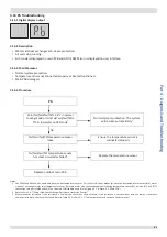
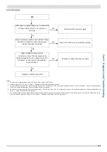
4.16.4 Procedure
Pb
Min(Tw/Two/Twi/Taf) ≤ 4°C in normal
cooling mode or min(Tw/Two/Twi/Taf) ≤
0°C in low water outlet mode
1
No
Tw/Two/Twi/Taf temperature sensor
loose
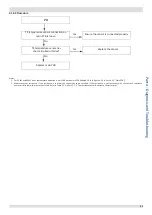
Tw/Two/Twi/Taf temperature sensor
has short-circuited or failed
3
Replace outdoor main PCB
Normal system protection. The system
will resume automatically
2
Ensure the temperature sensor is
connected properly
Replace the temperature sensor
Notes:
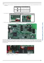
1. For 30kW and 60kW units, combined water outlet temperature sensor (Tw), Water side heat exchanger water outlet temperature sensor(Two), water
side heat exchanger water inlet temperature sensor (Twi) and water side heat exchanger anti-freezing temperature sensor(Taf, include Taf1 and Taf2)
connections are ports CN69 and CN31 on the main PCB (labeled 4 and 8 in in Figure 4-2.1 in Part 4, 2.2 “Main PCB”).
2. Refer to Part 3, 6.7 “Water Side Heat Exchanger Anti-freeze Protection Control”.
3. Measure sensor resistance. If the resistance is too low, the sensor has short-circuited. If the resistance is not consistent with the sensor’s resistance
characteristics table, the sensor has failed. Refer to Table 5-5.1 in Part 5, 5.1 “Temperature Sensor Resistance Characteristics”.