


103
Part 4 - Diagnosis and T
roubleshooting
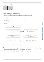
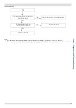
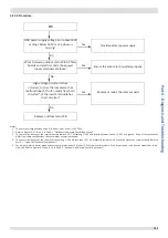
4.23.4 Procedure
H5
ODU power supply voltage at or above260V
or drops below 165V or or a phase is
missing
1
Wires between outdoor main PCB, AC filter
boards and electric control box power
supply terminals are loose
2
High voltage circuit error has
occurred, such as the compressor has
malfunctioned
3
, the fan motor has short-
circuited
4
, or the inverter module has
short-circuited
5
Replace outdoor main PCB
No
No
No
Yes
Yes
Yes
Provide normal power supply
Ensure the wires are connected properly
Replace or repair the relevant parts
Notes:
1. The normal voltage between A and N, B and N, and C and N is 165-265V.
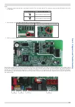
2. Refer to Figures 4-1.1 to 4-1.4 in Part 4, 1 “Outdoor Unit Electric Control Box Layout”.
3. The normal resistances of the inverter compressor are 0.7-1.5Ω among U V W and infinite between each of U V W and ground. If any of the resistances
differ from these specifications, the compressor has malfunctioned.
4. The normal resistances of the fan motor coil among U V W are less than 10Ω. If a measured resistance is 0Ω, the fan motor has short-circuited. Refer to
Part 2, 1 “Layout of Functional Components”.
5. Set a multi-meter to buzzer mode and test any two terminals of P N and U V W of the inverter module. If the buzzer sounds, the inverter module has short-
circuited. Refer to Figures 4-1.2and 4-1.4 in Part 4, 1 “Outdoor Unit Electric Control Box Layout”.


