background image

ZHEJIANG KAYO MOTOR CO., LTD.


www.kayomoto.com 

- 72 - 

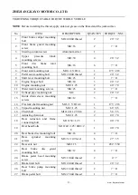
TIGHTENING TORQUE TABLE FOR THE WHOLE VEHICLE 
 

NOTE

: Before installing the thread, apply anti-rust grease on the thread and the joint surface 


No 

ITEM 

DESCRIPTION 

QUANTITY  TORQUE

NM


Front  brake  caliper  mounting 
bolt 

M8×40 full thread 

20

32 

Front  brake  guard  mounting 
screw 

M6×16 

7

11 

Steering column screw 

Aluminum silver 

Upper 

pressure 

block 

mounting screws 

M8×30 

20

32 

Front 

disc 

brake 

rotor 

mounting bolt 

M6×16 

7

11 

Front axle mounting nut 

M16×1.5×H14 

175

218 

Pedal seat mounting bolt 

M8×20 full thread 

20

32 

Shift lever mounting bolt 

M6×25 

7

11 

Engine hanger bolt 

M8×60 

20

32 

10 

Engine mounting nut 

M10×1.25 

40

70 

11 

Water tank mounting screws 

M6×25 

7

11 

12 

Exhaust pipe mounting nut 

M8 

20

32 

13 

Guide  chain  sleeve  mounting 
screws 

M6×12 

7

11 

14 

Flat fork shaft mounting nut 

M16×1.5×H14.8 

175

218 

15 

Tripod mounting nut 

M12×1.25 

68

85 

16 

Chain bolt 

M10×40×1.25 S14 

36

55 

17 

Adjusting chain nut 

M10×1.25 

40

70 

18 

Rear  reduction  and  frame 
connecting bolt 

M10×50×1.25 

40

70 

19 

Oval head bolts 

M10×42×1.25+Φ10×2

40

70 

20 

Rear brake disc mounting bolt 

M6×16 

7

11 

21 

Rear 

sprocket 

mounting 

screws 

M8×31 10.9 level 

27

35 

22 

Rear axle nut 

M22×1.5 

452

550 

23 

Rear 

brake 

disc 

guard 

mounting bolt 

M6×12 

7

11 

24 

Brake  pedal  head  mounting 
screw 

M5×10 full thread 

4

25 

Brake limit bolt 

M8×20 full thread 

20

32 

26 

Rear  brake  pump  mounting 
bolt 

M6×16 full thread 

7

11 

27 

Brake pedal bolt 

M6×25 full thread 

7

11 

Summary of Contents for KT250

Page 1: ...ZHEJIANG KAYO MOTOR CO LTD www kayomoto com 1 KAYO MOTO KT250 USER S MANUAL WWW KAYOMOTO COM...

Page 2: ...KAYO No part of this publication may be reproduced without authorization ZHEJIANG KAYO MOTOR CO LTD reserves the right to make changes at any time without notice and without incurring any obligation...

Page 3: ...s which can effectively prolong the service life of each component improve the engine performance and the reliability of the vehicle For the sake of technical development KAYO will reserve the right o...

Page 4: ...ORT 18 HOUR COUNTER 19 PREPAREING FOR USE 20 ADVICE ON FIRST USE 20 RUNNING IN PROCESS 20 RIDING INSTRUCTIONS 21 PREPARATION BEFORE RIDING 21 PRECAUTIONS FOR STARTING 21 PREACUSTIONS STOPPING 21 PREAC...

Page 5: ...TALLING THE FRONT SHOCK ABSORBER 29 REMOVING OR INSTALLING THE LINKAGE 29 CHECK THE FRONT STEERING 30 LUBRICATION AND INSTALLATION OF STEERING HEAD BEARING 30 REMOVING OR INSTALLING FRONT HEADLIGHT 31...

Page 6: ...COOLING SYSTEM PROFILE 49 REMOVING OR INSTALLING THE COWLING AND HOSE 49 CHECK ANTIFREEZE LEVEL 50 DRAIN OUT THE COOLANT 50 FILLING THE COOLING SYSTEM 51 INTRODUCING ABOUT THE ENGINE STRUCTURE 52 INS...

Page 7: ...o com 7 TROUBLESHOOTING 60 SELECTION AND RATIO OF ENGINE OIL 63 MOTORCYCLE CLEANING 64 STORAGE 65 PREPARING FOR LONG STORAGE 65 PREPARING FOR USE AFTER LONG STORAGE 65 MAINTENANCE POINTS 66 TIGHTENING...

Page 8: ...ant responsibility Please read this manual carefully Safety Messages preceded by a safety alert symbol and one of three signal words DANGER Indicates a danger that will immediately and invariably lead...

Page 9: ...them installed by an authorized KAYO workshop KAYO accepts no liability for any personal modification other products and any resulting damage or loss Our KT series products are specially designed for...

Page 10: ...14 15 16 17 18 No Name No Name 1 Front fender 10 Front brake caliper 2 Headlight 11 Front shock 3 Handlebar 12 Fuel tank 4 Vent pipe 13 Carburetor 5 Fuel tank cap 14 Gear shift lever 6 Fuel tank petc...

Page 11: ...ame 19 Taillight 28 Rear brake caliper 20 Rear fender 29 Aluminum swingarm 21 Exhaust pipe muffler 30 Triangle rocker arm 22 Seat 31 U shape rocker arm 23 Rear shock 32 Rear brake oil cup 24 Upper cla...

Page 12: ...NG KAYO MOTOR CO LTD www kayomoto com 12 ENGINE NUMBER The engine number of KT250 is located on the engine box behind the cylinder block VIN CODE Vin code of KT250 is located on the head pipe and Name...

Page 13: ...sually engaged two stage transmission six speed transmission International profile 1 N 2 3 4 5 6 Starting Electric Fuel control system PWK competitive carburetor Battery Lithium battery for high perfo...

Page 14: ...21 R 2 15 18 7050 high strength aluminum rim forged CNC wheel hub F brake system Double piston pump hydraulic brake system 240mm CNC ergonomic small handle bar R brake system Single piston pump hydrau...

Page 15: ...e the structure or affect the normal use FRONT DISC BRAKE hand brake lever front brake calipers The front disc brake is controlled by the hand brake lever which is fitted on the right side of the hand...

Page 16: ...ray one and fitted on the right side of the handlebars near the throttle grip It needs long press on the button when starting Attention When starting you should pinch the brake with your left hand to...

Page 17: ...ls on the oil tank switch is shown as the left picture ON indicates that the switch is opened for oil discharge OFF indicates that the switch is closed and the oil discharge is stopped RES indicates t...

Page 18: ...al The foot brake pedal is located on the right side of the engine and is functioned by stepping Note In actual use the brake operation should be mainly through foot brake use hand brake as a suppleme...

Page 19: ...the vehicle When in use the vehicle is centered and the single support is kicked to expand it and the entire vehicle is tilted to the left to make the single support contact the ground and support th...

Page 20: ...o each other correct the working gap and form a good smooth friction surface that can withstand larger loads Only after standard running in can the engine have excellent performance and reliability Th...

Page 21: ...ck tire pressure 13 Check battery level 14 Check the thickness of the front disc brake 15 Check the thickness of the rear disc brake 16 Check the torque of each fastener 17 Check the engine gear 18 Ch...

Page 22: ...efore shifting gears 2 Do not rev the engine when shifting gears 3 Do not shift gears in the corner PRECAUTIONS FOR BRAKING 1 Use foot brake as your first brake operation if necessary use hand brake a...

Page 23: ...oving parts chain handlebars etc and check for smooth operation Check the front disc brake fluid level p 49 Check the free play of brake handlebar p 48 Check whether the steering head bearing for loos...

Page 24: ...ic setting must be adjusted accordingly A small weight difference can be compensated by adjusting the rear shock absorber spring preload but if the weight difference is large the spring must be replac...

Page 25: ...int on the side of the rear fender and mark it as point 1 3 Measure the distance from Point 1 to the center of the rear axle and record it as A1 4 Remove the motorcycle from the rack MEASURE DISTANCE...

Page 26: ...2 The factory default value of D2 D2 KT250 50 100mm If D2 measured by the customer is lower than the factory value you should decrease the spring preload appropriately Conversely increase the spring p...

Page 27: ...driver Turn clockwise to increase compression damping Turn counterclockwise to decrease compression damping ADJUSTING THE REBOUND DAMPING OF FRONT SHOCK ABSORBER damping adjusting screw Adjusting Step...

Page 28: ...position 2 Use a 5mm hexagon wrench to remove the mounting screws Installing steps The installment should be carried out in the reverse order of removal REMOVING OR INSTALLING THE FRONT SHOCK ABSORBER...

Page 29: ...REMOVING OR INSTALLING THE FRONT SHOCK ABSORBER Removing Steps as follows 1 remove the front disc brake 2 Remove the front wheel 3 Loosen the mounting bolt on the linkage 4 Remove the front shock abso...

Page 30: ...rcycle head if it turns smoothly and there is no obstruction the motorcycle head turning is normal 3 If you find that the steering of the front of the car is obstructive remove the link plate to check...

Page 31: ...bracket 2 Remove the headlight 3 Pull out the connector between headlight and main cable Installing Steps The installment should be carried out in the reverse order of removal REMOVING OR INSTALLING...

Page 32: ...shock absorber and the frame 3 Loosen the connecting bolts of the U shaped rocker arm and the triangular rocker arm do not remove it 4 Remove the connecting bolts between the rear shock absorber and t...

Page 33: ...s a unique tool free maintenance design The side cover of the air filter can be removed or installed from the main body of the cover only by hands REMOVING OR INSTALLING THE AIR FILTER Removing Steps...

Page 34: ...filter hose with water and let it air dry 2 Clean the dust attached to the air filter sponge and soak the surface with air filter oil If the dust on the sponge is difficult to resolve you can also rep...

Page 35: ...the steps below Unscrew the mounting bolts of the muffler tube Unscrew the fixing bolts of the muffler tube Loosen the buckle at the connection between the muffler tube and the exhaust pipe Pull out...

Page 36: ...ween the chains to see if there is any sediment attached Clean the Chain Use a special cleaning detergent to wash the surface slit and gap of the chain wait until the chain is naturally air dried and...

Page 37: ...of maximum tension and re adjust the tension if necessary When checking the chain tension you should also check the chain guide and sprocket through visual inspection not limited to chain When the cha...

Page 38: ...ange the over worn chain guide and chain protector in order to ensure that the motorcycle works normally CHECK THE FRAME Checking Steps are as follows 1 Check whether the paint layer on the surface of...

Page 39: ...t on the vehicle rest your hands on the handlebars naturally and feel whether the position of the clutch grip and brake grip are comfortable or not If you feel difficult to steering adjust the positio...

Page 40: ...it seems that the air may be mixed into the oil pump or oil pipe You should check the entire brake system and take measures accordingly CHECK THE CABLE OF FRONT BRAKE LEVER The front brake lever can...

Page 41: ...thickness of the disc brake and compare it with the limit thickness required 3 If the thickness of disc brake is less than or equal to the limit thickness of the disc brake it must be replaced immedi...

Page 42: ...nsealed container The brake fluid may deteriorate when exposed to the air which will affect the braking effect Do not use used brake fluid NOTE You should change the brake fluid once a year even it ha...

Page 43: ...DISK LIQUID LEVEL Check the Liquid level through the Observing Hole The liquid level should higher than minimum level as required You should refuel it if it is insufficient NOTE Do not splash the bra...

Page 44: ...checking the thickness of the brake pads of the brake caliper the thickness should not be less than 1 mm If the thickness of the brake pads is lower than the minimum thickness the entire set of brake...

Page 45: ...ground and Stabilize it by using a motorcycle stand Remove front disc brake cover if have Loosen the front wheel axle pinch bolts Holding the front wheel with one hand withdraw the front wheel axle g...

Page 46: ...ise lines if the tire has a nail or glass fragments in it or if the sidewall is cracked 2 Check the tire thread worn if the height of tire plies lower than minimum require replace the tire right away...

Page 47: ...e adjacent spokes to check whether the tire spokes lack tension If you find that the spokes are loose and weak you must check all the spokes and both wheels If there is any further problem please cont...

Page 48: ...attery up and out Installing Steps The installment should be carried out in the reverse order of removal CHANGING THE BATTERY If you found bubble appears in the surface of the battery or it needs freq...

Page 49: ...ZHEJIANG KAYO MOTOR CO LTD www kayomoto com 49 COOLING SYSTEM COOLING SYSTEM PROFILE...

Page 50: ...Pet sun Antifreeze in the first place which freezing point is 25 WARNING Antifreeze is a kind of chemical reagent and may cause problem to human body pls read the instruction carefully before working...

Page 51: ...u can drain the coolant out of the engine and cooling system through adjusting the screw Main work Stand the motorcycle upright and allow the engine and coolant system to cool down Place a suitable co...

Page 52: ...ighten the tank cap WARNING DANGER OF SCALDING Do not remove the radiator cap screw or other cooling system components when the engine is hot Wait for the engine and cooling system to cool down If the...

Page 53: ...ng ring should be installed firmly with a tightening torque of 10 15N m and the exhaust port should not leak air during installation ENGINE MAINTENANCE AND ADJUSTMENT Inspection of installation bolts...

Page 54: ...0 1250Pa Minimum 1100Pa Low pressure indicates the following faults Excessive wear of the cylinder wall The piston or piston ring is worn The piston ring is stuck in the ring groove The valve is not p...

Page 55: ...properly DANGER Driving a motorcycle with a damaged throttle cable is undoubtedly a very dangerous behavior The normal throttle cable should have a free stroke of at least 10mm Start the engine and t...

Page 56: ...lows 1 Loosen the fixing bolts of the shift lever 2 Remove the shift lever 3 Turn the shift lever to a suitable position and install the spline 4 Tighten the shift lever fixing bolt INSPECTION OR REPL...

Page 57: ...th washing kerosene and then add new lubricating oil according to the regulations The thermal engine system of this engine must be lubricated with two stroke special engine oil The engine oil is mixed...

Page 58: ...wo stroke oil pump is related to the effective lubrication of the engine piston cylinder block crankshaft and other thermal parts so the inspection of the oil pump is particularly important The lubric...

Page 59: ...cap and then fill the oil Until the oil drips at the installation location of the oil pump at the bottom of the oil pump finally install the oil cap and then install the output oil pipe to the carbur...

Page 60: ...M10 20 24N m 2 Cylinder Head Cover Nut M8 22 26N m 3 Cylinder Block Fastening Nut M8 28 32N m 4 Primary Driving Gear Fasten Bolt M10 65 75N m 5 Clutch Tightening Nut M12 85 95N m 6 Balance Shaft Drive...

Page 61: ...arted or difficult to start Check whether the fuel flows into the carburetor Fuel does not flow into the carburetor No gasoline in the fuel tank Blocked tubing from the fuel tank to the carburetor Fue...

Page 62: ...e engine performs poorly at low or idling speeds Check valve timing and valve clearance Incorrect Improper valve clearance adjustment or poor quality of rocker arm adjustment screws Correct Improper a...

Page 63: ...ow Blocked fuel tank cap vent Check if the filter and carburetor nozzle are blocked Blockage Blocked carburetor measuring hole Unblocked Float stuck Filter blocked Check gas timing Incorrect Adjust ga...

Page 64: ...combustion The difference between two stroke engine oil and four stroke engine oil is as follows Item Two stroke engine oil Four stroke engine oil Flash point 1 low flammable high flash point 200 Thi...

Page 65: ...the run in period 30 1 NOTE The oils shown above are only used for mixing with gasoline not for gearbox lubrication KAYO chooses SJ 5W 40 four stroke engine oil as the gear oil for the engines of var...

Page 66: ...uspended If this condition cannot be achieved you can use cardboard to pad under the motorcycle tires 9 Cover the motorcycle to prevent dust and dirt 10 Move the motorcycle into a dry room and place i...

Page 67: ...has deteriorated Drain the old fuel and add new fuel Dirt or wet spark plug Clean or dry the spark plug if necessary replace the spark plug Engine water intake First drain the mixed fuel out the engi...

Page 68: ...leaks in the cooling system Clogged water tank fins Use low pressure water to clean the fins of the water tank and replace them if necessary Unbalanced engine operation The spark plug is dirty damage...

Page 69: ...box gear does not mesh Clutch abnormality Contact KAYO Service Center The fork is bent or stuck Check and adjust the fork Damaged gear lever Replace the gear lever Damaged gear shift drum Replace the...

Page 70: ...ssure Damping adjustment error Re adjust damping There is abnormal noise when the motorcycle is driving Improper chain adjustment Re adjust the chain tension Chain wear Replace the chain and front and...

Page 71: ...Center Improper steering adjustment Check and readjust Bent steering shaft Contact KAYO Service Center There is a problem with the fork Contact KAYO Service Center Vehicle is not aligned Re adjust the...

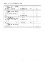
Page 72: ...10 Engine mounting nut M10 1 25 2 40 70 11 Water tank mounting screws M6 25 4 7 11 12 Exhaust pipe mounting nut M8 2 20 32 13 Guide chain sleeve mounting screws M6 12 3 7 11 14 Flat fork shaft mounti...

Page 73: ...tage stabilizer mounting bolt M6 25 full thread 2 7 11 32 Electric door lock bracket bolt M6 12 2 7 11 33 Fuel tank switch mounting screws M5 12 full thread 2 4 7 34 Front fender bolt M6 12 4 7 11 35...

Reviews: