background image

Instructions for use Primus 1058 Life

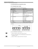
4 Operation | 4.7 Using functions through the menu

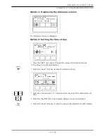
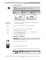
Option 1: Displaying the firmware version

The firmware version is displayed

Option 2: Setting the time of day

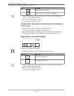
Press the "SET" (S2) key to change the values of minutes and hours.

ð

The value to be changed flashes.

Press the "Save" (S4) key to save the selection made.

Press the "reduce value" or "increase value" key to set the marked time of
day.

Press the "SS:MM" (S1) key to switch between hours and minutes.

Press the "Save" (S4) key to save the values and switch to the SET display.

63 / 126

Summary of Contents for KaVo Primus 1058 Life TM

Page 1: ...Instructions for use Primus 1058 Life...

Page 2: ...Manufacturer Kaltenbach Voigt GmbH Bismarckring 39 D 88400 Biberach www kavo com Distributed by KaVo Dental GmbH Bismarckring 39 D 88400 Biberach Phone 49 0 7351 56 0 Fax 49 0 7351 56 1488...

Page 3: ...on 18 3 1 Treatment unit versions 18 3 1 1 KaVo Primus 1058 Life TM 18 3 1 2 KaVo Primus 1058 Life S 18 3 1 3 KaVo Primus 1058 Life C 19 3 1 4 KaVo Primus 1058 Life C with right side set up kit 19 3 2...

Page 4: ...ing the MEMOspeed menu optional 69 4 7 4 Using the CONEXIOcom optional 75 4 8 Using function through the dentist or assistant unit 76 4 8 1 Using the hygiene functions 76 4 8 2 Using lamp and X ray im...

Page 5: ...st 106 7 2 5 Assessment and documentation 109 8 Appendix Additional measuring sites 111 8 1 Additional scanning sites SL X in the protective conductor measurement 111 8 2 Additional measuring sites AP...

Page 6: ...uctions TI Technician s instructions SC Safety checks IEC International Electrotechnical Commission RI Repair instructions RK Retrofitting kit AS Assembly kit CK Conversion kit EP Enclosed parts EMC E...

Page 7: ...not be held liable for defects and their consequences due to natural wear improper cleaning or servicing non compliance with operating servicing or connection instructions calcification or corrosion c...

Page 8: ...oned obligations will mean that the damage will be considered to have arisen following delivery in accordance with the General German Freight For warders Terms and Conditions Art 28 Outside Germany No...

Page 9: ...e keep the packaging in case you need to return the product for servi cing or repair The symbols printed on the outside are for transportation and storage and have the following meaning Transport upri...

Page 10: ...ed as shown below DANGER In cases which if not prevented directly lead to death or severe in jury WARNING In cases which if not prevented could lead to death or severe in jury CAUTION In cases which i...

Page 11: ...n for use for hardware and software and are installed and set up according to the descriptions of these components in the case of repairs the requirements of IEC 62353 Recurrent tests and tests before...

Page 12: ...romag netic compatibility of electrical medical devices we must draw your attention to the following points Medical electrical devices are subject to special precautions concerning the electromagnetic...

Page 13: ...ories must be used exclusively Accessories Use Name Material number Monitors Monitor 22 KaVo Screen HD 1 011 0302 Monitor 19 KaVo Screen One 1 011 0300 Cameras Intraoral camera ERGOcam One 130 ERGOcam...

Page 14: ...d functional parts If functional parts are damaged it can cause additional damage or personal in jury Check the device electrical cables and any accessories regularly for pos sible damage to the insul...

Page 15: ...older or operating device In creased risk of infection from ill patients Be aware of the arrangement of the instruments when you reach for the tray holder or operating device WARNING Health damage due...

Page 16: ...50 CAUTION Electrical power Electrical shock from incorrectly connecting a non medical system to the freely usable USB interfaces of the device if any Connect any IT device to the medical system in ac...

Page 17: ...ion up to 0 02 CAUTION Long stay in the patient chair Decubitus formation Take precautions against the formation of decubitus in long treatments CAUTION Risk of injury when the dental chair or headres...

Page 18: ...tructions for use Primus 1058 Life 3 Product description 3 1 Treatment unit versions 18 126 3 Product description 3 1 Treatment unit versions 3 1 1 KaVo Primus 1058 Life TM 3 1 2 KaVo Primus 1058 Life...

Page 19: ...Instructions for use Primus 1058 Life 3 Product description 3 1 Treatment unit versions 3 1 3 KaVo Primus 1058 Life C 3 1 4 KaVo Primus 1058 Life C with right side set up kit 19 126...

Page 20: ...tructions for use Primus 1058 Life 3 Product description 3 2 Patient chair Standard and COMPACTchair 20 126 3 2 Patient chair Standard and COMPACTchair Headrest Backrest Chair base Seat Arm rest optio...

Page 21: ...3 Device body with patient unit Patient element Unit body The central control is housed in the unit body Pressurised water bottle supplementary equipment Spittoon bowl Tumbler filler Supply element Cu...

Page 22: ...ntist unit versions 22 126 3 4 Dentist unit versions 3 4 1 TM C table Handle Turbine multiflex coupling INTRA LUX motor KL 703 or INTRA LUX motor KL 701 Ultrasonic scaler Three function handpiece or m...

Page 23: ...te The holder assignment and arrangement of the instruments can be changed as needed and does not have to follow the picture Control element Triple function handpiece or multi functional handpiece Tur...

Page 24: ...Assistant element Versions 24 126 3 5 Assistant element Versions 3 5 1 Standard assistant unit Three function or multifunctional handpiece Spray mist suction Control element Saliva ejector Satelec Min...

Page 25: ...ption 3 5 Assistant element Versions 3 5 2 Assistant element right left optional only in conjunction with patient chair Standard Triple function handpiece Spray mist suction Control element Saliva eje...

Page 26: ...ee function handpiece 3F handpiece MF handpiece hose Gripping sleeve Media buttons air water Labelled blue Three function hand piece 3F handpiece Cannula 3 7 Multifunctional handpiece MF handpiece MF...

Page 27: ...ype 1 radiological viewing device in accord ance as defined in DIN 6856 3 3 9 Controls 3 9 1 Dentist elements Dentist element TM C table A Group of keys for the dental chair B Group of keys for menu s...

Page 28: ...ys for the handpieces D Group of keys for the dental chair E Group of keys for illumination F Group of keys for hygiene 3 9 2 Assistant unit A Group of keys for hygiene B Group of keys for illuminatio...

Page 29: ...t position AP key activate automatic posi tion Backrest down key AP 1 key automatic position 1 Backrest up key AP 2 key automatic position 2 Collapsed position key Group of keys for illumination Key N...

Page 30: ...the handpieces timer Key Name Control element Preselected spray but ton Dentist element Direction of motor rota tion button Dentist element Timer key Dentist element and assistant element Group of key...

Page 31: ...the Chair motion function Blown air AP foot switch Moves the dental chair into automatic posi tion Sets the preset blown air chip blower Cross switch Coun terclockwise motor ro tation Changes the posi...

Page 32: ...cation plate 32 126 Internal attachment site for rating plate Outside attachment site for rating plate SN Serial number Read and take note of the content of accompanying documents Please note the inst...

Page 33: ...use ratings The depend on the mains voltage and are either T10 H or T6 3H 100 V 110 V 120 V 130 V T10H 220 V 230 V 240 V T6 3H For disposal information see also Purpose Intended use CE mark according...

Page 34: ...e BF Type Device type SN Year of manufacture serial number REF Material number Labelling and marking of the three function handpiece and multifunctional handpiece Company logo of the manufacturer SN S...

Page 35: ...g plate and identification plate Rating plate Service table 1568 Site for affixing the rating plate 4 5 6 7 Device type Material number Year and month manufactured Serial number HIBC Code Read and tak...

Page 36: ...anufactured Serial number Material number Supply voltage frequency Power Disposal instructions CE mark Serial number Year and month manufactured 3 11 Technical data Drilling template and setup plan In...

Page 37: ...ive conductor above floor See DIN VDE 0100 710 1000 mm Heat emission 360 to 3 240 kJ h Heat emission 900 kJ h Mark of approval CE DVGW VDE Foot control IPX1 Protection against water drips Triple funct...

Page 38: ...the treatment water and the mi crobial re contamination of the public drinking water network Note In conjunction with the DVGW water block with integrated water germ re duction a water germ reduction...

Page 39: ...1717 each unit that is not listed by DVGW must be provided with an upstream type AA AB or AD safety device The DVGW water bottle kit is certified see the following list When establishing a water conn...

Page 40: ...e min 80 Nl min Pressure dew point 30 C compressor with dry air system Oil content 0 1 mg m3 oil free compressor Contamination 100 particles m3 at particle sizes of 1 to 5 m Customer site air filtrati...

Page 41: ...n connection 40 mm Suction connection above floor 20 mm Operating environment WARNING Inappropriate operating conditions Impairment of the electrical safety of the device It is essential to comply wit...

Page 42: ...and storage conditions Ambient temperature 20 to 55 o C Relative Humidity 5 to 95 non condensing Air pressure 700 hPa to 1 060 hPa Weight Treatment centre TM with patient chair Standard 223 kg gross 1...

Page 43: ...lux de Luxe G5 Day light L8W 954 Light field dimensions 300 mm x 150 mm in accordance with DIN 6856 3 Case dimensions 340x216x48 in accordance with DIN 6856 3 Operating light KaVoLUX 540 LED See also...

Page 44: ...in switch The display of the dentist element shows the preselected basic menu The green LED Device turned on lights up on the assistant element Basic menu without MEMOspeed basic menu with MEMOspeed a...

Page 45: ...be swung up CAUTION The patient s hands are in a bad position when the chair is rising Danger of crushing fingers between the backrest and arm rest Make sure that the patient is sitting in the right...

Page 46: ...t is aware of the headrest being adjusted Patients need to raise their head slightly during adjustment Use both hands to adjust the headrest Push in or pull out the headrest depending on the patient s...

Page 47: ...can be adjusted Press the lock button and push in or pull out the headrest depending on the patient s height Note The service technician can adjust the braking force Press the lock button and swing th...

Page 48: ...d treatment personnel when changing the patient s position CAUTION Risk of injury when moving the patient or patient chair The patient or treatment personnel can be pinched or crushed Position all mov...

Page 49: ...ading it Do not subject the patient chair to a load exceeding its limit Standard pa tient chair 185 kg COMPACTchair patient chair 135 kg Do not subject the patient chair to dynamic loads CAUTION Dange...

Page 50: ...ition 2 Move to the collapsed position Briefly press the desired button Chair automatically moves to the stored position Upon arrival at the stored position the display diode on the button is turned o...

Page 51: ...assistant unit Note The automatic position Last position is saved on the LP button Press the LP button for the chair to automatically move to the last position before the rinsing position The LP butt...

Page 52: ...SP rinsing position Move the chair when the instrument is mounted Press the SP foot operated button or Press the LP foot operated button The chair moves into the selected automatic position Move the c...

Page 53: ...position is saved to the foot operated button or Hold down the foot pedal and foot operated button LP and simultan eously press any button for an automatic position AP 0 AP 1 AP 2 or SP on the dentist...

Page 54: ...the switching function The treatment personnel must move outside of the chair s swivelling range whenever the chair moves The safety cut offs can be found at the following places on the treatment unit...

Page 55: ...ment LED on dentist ele ment Patient unit pivoted over the patient chair Assistant element Backrest Bracket on the foot control Bench support seat cushion Foldable part of the bench The safety shutoff...

Page 56: ...osition cannot be changed with the key wheels when a safety shutoff is activated Exception The patient unit safety switch only stops the upward and down ward movement of the patient chair The backrest...

Page 57: ...the dentist element CAUTION Risk of injury when the dentist or assistant element is moved The patient or office staff may be injured or bruised Monitor the patient and office staff when moving the den...

Page 58: ...e is restricted by the length of the lines and hoses that connect the cart to the base of the device Only move the cart within this range To change the position of the cart hold the cart by the bow ty...

Page 59: ...hazard Each time before the chair is adjusted automatic and manual swing the manually adjusted patient s unit into resting position Note When the patient unit is swung over the patient chair the safet...

Page 60: ...element Tray support Air nozzle holder The support for the tray holder is an optional accessory 4 6 2 Moving the assistant element right left optional CAUTION Pinching from the treatment chair The tre...

Page 61: ...nging range Adjusting the height of the assistant element right left optional Note Handpieces may drop out of the holders while the assistant element is being moved especially during adjustment of the...

Page 62: ...y mode Setting the time of day display mode Time of day only Time of day without seconds 5 Language Set menu language Deutsch English Italiano Fran ais 6 LCD Set contrast of LCD display 7 Licenses Dis...

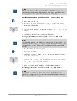
Page 63: ...ing the time of day Press the SET S2 key to change the values of minutes and hours The value to be changed flashes Press the Save S4 key to save the selection made Press the reduce value or increase v...

Page 64: ...ve the selection made Press the Decrease value or Increase value key to set the marked value Press the SS MM S1 key to switch between day month and year Press the Save S4 key to save the values and sw...

Page 65: ...ollowing languages can be selected Deutsch English Italiano Francais Press the Save S1 key to save the values Option 6 Setting the display contrast Press the reduce value or increase value key to set...

Page 66: ...low each display field there is a key for selecting the displayed operating function Standby menu with MEMOspeed Standby menu without MEMOspeed Menu function selection keys Display Select dentist The...

Page 67: ...elected dentist is only displayed very small in the level switching symbol Note The device automatically saves the activation of level switching for the cur rent dentist Note Level switching is deacti...

Page 68: ...ing functions through the menu 68 126 Press the selection keys and to switch between multiple status messages Press the OK selection key to exit from the display of status messages Error messages in t...

Page 69: ...y Direction of motor rotation Preselected spray Ultrasonic scaler Spray on off Intensity with level switching only Multifunctional handpiece Heating on off only with a corresponding setting in service...

Page 70: ...s on No cooling One LED is on Spray air cooling status Both LEDs are on Spray cooling status Changing motor settings in the menu Note Following instructions for use service instructions and installati...

Page 71: ...imal and maximal speed Press the key for Decrease value to decrease the speed or Press the Increase value key to increase the speed The speed is shown in the display Press the Save key to save the val...

Page 72: ...ction of motor rotation is reversed each time the cross switch and or the Direction of motor rotation key is actuated counterclockwise rota tion clockwise rotation The LED is on when CCW motor rotatio...

Page 73: ...shown on the display Define operating mode PiezoLED only Note The selection of the mode depends on the treatment method and the tip used For information about the selection of an operating mode pleas...

Page 74: ...u Briefly press Preselect level key to select the level Take the multifunctional handpiece off the holder Press Preselect level button for 4 seconds in order to change settings The display changes to...

Page 75: ...It is also feasible to automat ically transfer the patient from your invoicing programme to CONEXIO For de tails on the configuration please refer to the CONEXIO installation instruc tions If no patie...

Page 76: ...ia or Slida interface to CONEXIO in the re spective treatment room The patient is now automatically activated on the treatment centre This might be an option of your patient management sys tem that is...

Page 77: ...t filling the tumbler Tumbler filling is started and then stopped after the saved period of time Default 5 s An on off operation is not supported Press the Tumbler filling key for more than 4 seconds...

Page 78: ...ing light using the Operating light key on the assistant element Only then the operating light can be operated by means of the sensor and the control panel of the operating light 4 8 3 Using the bell...

Page 79: ...e S4 Switches counter timer function Direction of counting 4 8 5 Saving handpiece settings without MEMOspeed The following settings can be individually saved for the instruments Handpiece Setting Turb...

Page 80: ...oling status Both LEDs are on Spray cooling status Save the cooling status Press the Save S1 key until you hear a beep Setting the motor Note The speed is not shown in the display cannot be saved The...

Page 81: ...the speed of the turbine See also 2 4 8 5 1 Setting the turbine Page 79 Selecting the operating mode PiezoLED only Note The selection of the mode depends on the treatment method and the tip used For i...

Page 82: ...tion the dental chair using the button cross or 4 way switch 4 9 3 Preselect dentist Requirement All instruments are in their holder Hold down the foot pedal and press the stirrup switch Each time the...

Page 83: ...r from the holder The handpiece is active Press the Blown air foot operated button As long as the foot operated button is pressed blown air exits from the re moved handpiece does not apply to PiezoLED...

Page 84: ...view Capture Mode Toggles between the recording modes video recording and image re cording Screen display Toggles between full screen and normal view Save image video Press briefly freezes the live i...

Page 85: ...of the service table is 2 kg The presence of the locking mechanism increases the maximum load to 5 kg 1 2 Rotate the rotary knob in counterclockwise direction to lock the service table in place Rotate...

Page 86: ...Instructions for use Primus 1058 Life 4 Operation 4 10 Service table 1568 optional accessory 86 126 Dimensions and swing ranges in mm...

Page 87: ...Instructions for use Primus 1058 Life 5 Preparation methods DIN EN ISO 17664 5 Preparation methods DIN EN ISO 17664 Note The preparation methods can be found in the care instructions 87 126...

Page 88: ...ion 95 Separation D RR CS1 Separation using a solids collector Solids collector kit Wastewater solids collector for wet suctioning External suction Wastewater and wet suction air are drawn from a cent...

Page 89: ...COMFORTbase 404L COMFORTbase 404S For connection of INTRA LUX motor KL 701 motor KL 703 LED COMFORTdrive 200XD Assembly kit INTRA LUX motor KL 703 LED Brushless motor with light Assembly kit INTRA LUX...

Page 90: ...during servicing during inspections and maintenance following repairs on the occasion of recurrent tests Note With regard to devices that have not been manufactured in accordance with IEC 60601 1 DIN...

Page 91: ...he person responsible for putting the system together must employ the necessary measuring parameters and measuring proced ures defined in IEC 60601 1 DIN EN 60601 1 Note Each individual device in an M...

Page 92: ...easurement of the insulation resistance in accordance with IEC 62353 need not be carried out This check is covered by the measurement of the leakage current provided a safety tester specified in IEC 6...

Page 93: ...terioration in values is determined 7 2 Instructions for the safety check 7 2 1 Preparatory measures to be undertaken on the device WARNING Electrical power Death or injury from electric shock Before...

Page 94: ...no longer included in DIN EN 62353 2015 IEC 62353 2015 Visual inspection and appraisal of the medical device and accessories The following list is for exemplary purposes and makes no claim of being co...

Page 95: ...not exceeded Check of legibility and completeness of the safety related labels Check if all safety related markings plates and labels are present and legible Check if the rating plate and serial numb...

Page 96: ...and tests in a manner that will ensure that there will be no danger to the testing personnel patients or other persons Note The safety tester must comply with the requirements defined in DIN EN 62353...

Page 97: ...ed The adapter cable is included in the delivery of the KaVo measuring cable and is required for older treatment centres that are not equipped with an X2 connector Connecting the safety tester with Ka...

Page 98: ...e power supply cord to be voltage free Disconnect L N on terminals X1 1 and X1 2 Connect the safety tester directly to terminals X1 1 L and X1 2 N and protective earth conductor terminal PE Note The m...

Page 99: ...he protective conductor PE during the measurement on the treatment centre Primus 1058 Life as all relevant parts are connected to the PE at the factory and are included in the test ACPs on treatment l...

Page 100: ...e kept handy for possible use should be taken into consideration and the respective PE meas ured Protective earth measurement The protective conductor resistance must be measured at the following part...

Page 101: ...heck Test instructions 7 2 Instructions for the safety check Scan the treatment centre with the test tip Measuring points on the device base Main switch holding plate Stand cover base plate Surroundin...

Page 102: ...ns 7 2 Instructions for the safety check 102 126 Scanning the patient chair with the test tip 1 2 3 Top part of the chair Base plate of chair base Chair switched mode power supply COMPACTchair measuri...

Page 103: ...ist element S Fixing screw on the underside of the dentist ele ment Dentist element TM Fixing screw on the underside of the dentist ele ment Dentist element C Fixing screw on the underside of the dent...

Page 104: ...of the handle sup port when the gripping sleeve has been removed Operating light EDI MAIA No measuring points need to be scanned on the operating lights EDI and MAIA Touch monitor with test tip Scan t...

Page 105: ...njury from electric shock Prior to connecting the treatment centre to the safety tester disconnect the treatment centre from the mains supply network Applied part leakage current Alternative measuring...

Page 106: ...asurement of the leakage current of the casing whereby the same per missible values are applicable 7 2 4 Functional test The following conditions must be met in all function tests The basic function o...

Page 107: ...he safety check Patient chair Standard Safety shutoff for the standard patient chair Item No Safety switch off ac tuated LED on assistant element LED on dentist ele ment Patient unit pivoted over the...

Page 108: ...safety shutoff the chair immediately stops moving The fact that the safety shutoff has been activated is displayed by the corres ponding display flashing on the dentist or assistant element Item No Sa...

Page 109: ...e and signature of test engineer There is a copy of a test report template at the end of the chapter on Safety Checks KaVo recommends the use of this template Note Following testing repair or adjustme...

Page 110: ...ons for use Primus 1058 Life 7 Safety check Test instructions 7 2 Instructions for the safety check 110 126 Unit leakage current replacement measurement Leakage current of applied part replacement mea...

Page 111: ...r measure ment 8 Appendix Additional measuring sites Note Regarding accessories which are not listed here comply with the specifica tions of the relevant instructions for use 8 1 Additional scanning s...

Page 112: ...g light assembly kit 2 3 Base plate for the ceiling adapter Surroundings of the protective con ductor connector Surroundings of the protective con nector terminal 8 2 Additional measuring sites AP X f...

Page 113: ...piece must be activated during the EPA measure ment Note Additional measuring points AP X need to be taken into consideration in the presence of accessories e g if third party devices are connected ca...

Page 114: ...ntrol panel flashes Check the safety shutoff and eliminate the reason for the shutoff Display without indic ator Bus hardware error Turn the device off and on Call the service technician to look into...

Page 115: ...insufficient The spray nozzles are dirty clogged Clean the spray nozzles according to the ac companying instrument operating instructions Leaks in instruments O rings at MULTIflex or motor coupling gr...

Page 116: ...ce See Operating Instructions of the amalgam separator Emergency shut off of the bowl valve only when external suction is installed Call a service technician ERGOcam does not work PC is switched off T...

Page 117: ...a technician fixed the leak Malfunction Cause Remedy Display shows ID 33 No CAN node and or in ternal communication is faulty Call a service technician Display shows ID 64 Water is shut off Turn water...

Page 118: ...y Display shows ID XX This error is not de scribed in this chapter Call a technician Display shows CAN fail Internal communication error Turn the unit off and on again consult a ser vice technician ac...

Page 119: ...suitable for use in all equipment including devices in living areas and suit able for equipment which is dir ectly connected to supply mains that also supply buildings used for residential purposes E...

Page 120: ...11 5 UT 95 interruption for period 40 UT 60 interruption for 5 periods 70 UT 30 interruption for 25 periods 5 UT 95 interruption for 5 s 250 periods 5 UT 95 interruption for period 40 UT 60 interrupt...

Page 121: ...m rated power is not included in the above table the recommended safe distance d in metres m can be calculated using the equation for the respective column where P is the maximum rated power of the tr...

Page 122: ...agation of electromagnetic waves is subject to absorption and reflection by buildings objects and people a The ISM frequency bands for industrial scientific and medical applications between 150 kHZ an...

Page 123: ...us 1058 Life 10 Data on electromagnetic compatibility according to EN 60601 1 2 10 4 Immunity to electromagnetic interfer d In the frequency range of 150 kHz to 80 MHz the field strength should be les...

Page 124: ......

Page 125: ......

Page 126: ...1 011 8573 Fk 20181009 6 en...

Reviews: