background image

2400 – 4400 VFX DECORATIVE AERATOR

MANUAL

884170 / 2021.1.1

9

C85 / C95 NON-METALLIC CONTROL PANEL TIMER
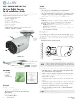
TIME CLOCK SETTING 

To set the current time, turn the inner dial clockwise. Do not set the time by rotating “outer” dial. Turn the min

-

ute hand or small plastic inner dial clockwise until the time of day on the outer dial is aligned with the triangle marker on the inner dial 

(two o’clock position). Example for 10:00 AM: Turn the minute hand clockwise until 10:00 AM is aligned with the triangle on the inner 

dial. The hour and the minute dial will show exactly 10:00.

PROGRAMMING 

The 24-hour dial has quarter-hour divisions and AM/PM indications. The time switch is programmed by pushing the 

captive trippers to the outer ring position for the entire period that the aerator is to be turned “ON,” i.e. 15min for each tripper on the 24-

hour dial. When the tripper is pushed to the inside, the switch is in the “OFF” position.

PROGRAMMING WITH MANUAL OVERRIDE SWITCH

 Your timer may have a 3-way manual switch or a 2-way manual switch. 

•  AUTOMATIC MODE: In order to operate the time clock in the automatic mode, the manual switch must be in the automatic 

position-see diagram� 

• 

MANUAL MODE: For the 3-way switch, with the manual override switch in the lower position, marked “O”, the time clock out

-

put will remain permanently OFF. In the upper position, marked “I”, the time clock output will remain permanently ON. For the 

2-way switch, with the manual override switch in the lower position, marked “ON,” the time clock output will remain permanent

-

ly ON�

11 


Triangle marker

Captive trippers (in the ON position)

Back to Contents

Summary of Contents for 2400VFX

Page 1: ...FX Decorative Aerator 2400VFX 3400VFX 3400HVFX 4400VFX 4400HVFX 800 Deere Rd Prescott WI 54021 715 262 4488 sales kascomarine com www kascomarine com Document number 884170 Operation Maintenance Manua...

Page 2: ...rd to either side of the float If you have a light kit make sure that the unit cord is tied to one side of the float and the light cord to the other for balance It is extremely important to test the G...

Page 3: ...conductor and or a grounding type attachment plug To reduce the risk of electrical shock be certain the unit is properly connected to the Kasco supplied control panel refer to the instructions include...

Page 4: ...210 4 1 4 split washers 7 840537 5 1 4 3 4 OD flat washer 10 251300 6 1 4 20 x 1 3 4 hex head screw 3 475630 7 Bottom screen section 3 361540 8 1 4 20 nut 3 840536 9 8 nut 6 771034 10 8 flat washer 12...

Page 5: ...with legs 2 Lock washer goes between bolt and flat washer Tighten down in 4 places 3 4 5 9 10 11 12 10 3 Turn over Bring bottom screen sections together 8 4 5 5 6 ASSEMBLY INSTRUCTIONS 4 Tighten down...

Page 6: ...by sinking them further below the surface UNIT INSTALLATION INSTRUCTIONS After unit is installed in the water connect the power cord to a properly installed Kasco control panel C 85 C 95 etc with buil...

Page 7: ...onnect switch to provide circuit protection and a disconnection means C 85 panel requires at least a 30amp protected circuit feeding the panel C 95 panel requires at least a 40 amp protected circuit f...

Page 8: ...n the ON position 2 If the GFCI tests okay restore power by pushing the RESET button back in THE RESET BUTTON MUST BE PUSHED FIRMLY AND FULLY INTO PLACE UNTIL IT LOCKS AND REMAINS DEPRESSED AFTER PRES...

Page 9: ...ippers to the outer ring position for the entire period that the aerator is to be turned ON i e 15min for each tripper on the 24 hour dial When the tripper is pushed to the inside the switch is in the...

Page 10: ...50 5A Prop 2400VFX 1 240595 5B Prop 3400VFX 3400HVFX 1 340595 5C Prop 4400VFX 4400HVFX 1 440600 6A Top disk 2400VFX 1 241025 6B Top disk 3400VFX 3400HVFX 1 241035 6C Top disk 4400VFX 4400HVFX 1 241045...

Page 11: ...unit upside down if it will sit for a long period of time to ensure continued oil lubrication of seals units that sit upright for many months or years have a greater likelihood of seals drying out CLE...

Page 12: ...riginal receipt and registering the equipment online at kascomarine com under the Warranty Information section Once warranty coverage has been established the unit may be sent to Kasco Marine or any K...

Page 13: ...t before the work is performed All estimates that are rejected for repair will be destroyed unless otherwise directed by the customer Rejected equipment can be returned at the customer s expense for s...

Page 14: ...aker single phase units only Each Kasco aerator has a Thermal Overload built in that will turn the unit off when it overheats Once the unit has cooled down it will start back up If you are noticing th...

Page 15: ...customer to ship and pay freight to Kasco Note Contact Information should be that of the person or company to contact for repair information Company name Contact name First name Last name Address Str...

Reviews: