background image

 9.801-509.0 - C  •  Karcher Operator's Manual

MANU

AL


PRESSURE W

ASHER 


10

INSTALLATION

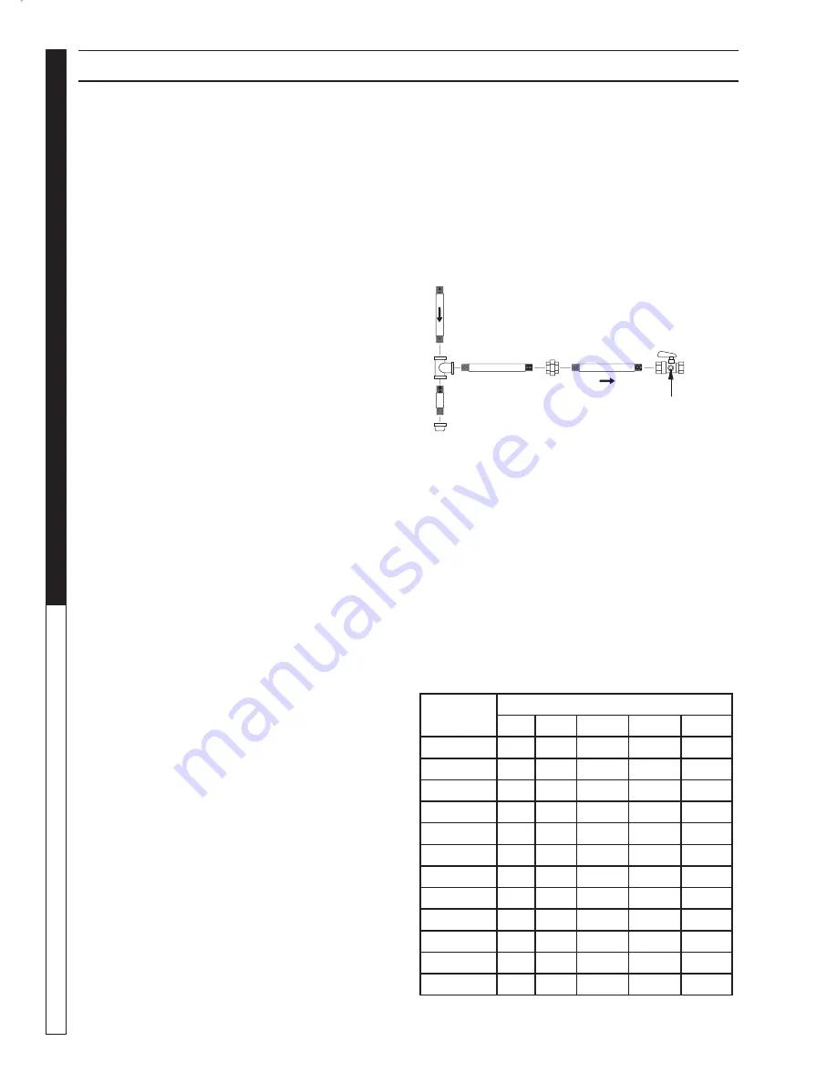
Install a gas union in the gas line adjacent to and up-
 stream from the con trol manifold and downstream from 
the man u al main shut-off valve. A 1/8" NPT plugged 
tap ping ac ces si ble for test gauge connection shall 
be in stalled im me di ate ly up stream of the gas supply 
con nec tion for the pur pose of de ter min ing the gas 
supply pres sure to the burn er, and to pre vent damage 
to gas valve.

If a manual gas shut off valve is not in the gas supply 
line within six feet of the machine and in an ac ces si ble 
lo ca tion, one shall be installed.

Figure 1: Union Location

Union Connection

The following pipe sizes are just rec om men da tions. 
Always consult a local plumber and vent ing con trac-
 tor for local codes and regulations during in stal la tion.

Pipe Sizing Chart for Natural Gas

The following chart is based on gas pressure in the 
range 0-0.5 psi, specifi c gravity of 0.6 and pressure 
loss of 0.5" W.C. Numbers are for straight schedule 
40 pipe; fi ttings further reduce capacity. For example, 
in 1" size, an elbow is equivalent to about 2.6 feet of 
pipe and a tee is equivalent to about 5.2 feet of pipe.

Maximum capacity of pipe in cubic feet/hr of natural gas 

(Multiply values by 1000 to get nominal BTU/hr capacity.

Place machine in a convenient location providing am ple 
support, drainage and room for maintenance (pgs 8-9).

Location:

The location should protect machine from damaging en-
 vi ron men tal con di tions, such as wind, rain and freez ing.

  1. The machine should be run on a level surface 

where it is not readily infl uenced by outside sourc-
 es such as strong winds, freezing tem per a tures, 
rain, etc. The machine should be located consider-
ing ac ces si bil i ty for the re plac ing of com po nents 
and the re fi ll ing of detergents, ad just ments and 
main te nance. Nor mal precautions should be tak en 
by the op er a tor of the machine to prevent excess 
moisture from reach ing the machine.

  2. It is recommended that a partition be made be-

 tween the wash area and machine to prevent direct 
spray from the spray gun from coming in contact 
with the ma chine. Ex cess moisture reach ing the 
power unit or electrical con trols will re duce the 
machine’s life and may cause elec tri cal shorts.

  3. During installation of the machine, be ware of 

poor ly ven ti lat ed lo ca tions or areas where ex haust 
fans may cause an insuffi cient supply of ox y gen. 
Suf fi  

cient com bus tion can only be ob tained when 

there is a suf fi  

cient sup ply of oxygen available for 

the amount of fuel be ing burned. If it is necessary 
to install a machine in a poor ly ven ti lat ed area, out-
 side fresh air may have to be piped to the burn er 
and a fan in stalled to bring the air into the area.  

  4.   Do not locate near any combustible material. Keep 

all fl ammable material at least 20 feet away.


  Allow enough space for servicing the machine.


  Local code will require certain distances from fl oor 

and walls. (Two feet away should be adequate).

WARNING: Avoid small areas or near exhaust fans. 

Gas Codes:

Confer with local gas company and with proper mu-
 nic i pal offi cials regarding any specifi c code or reg u la-
 tions gov ern ing the installation. The in stal la tion must 
con form to lo cal codes (NFPA 54).

Electrical:

The machine, when installed, must be elec tri cal ly 
ground ed in accordance to local codes. Check for 
prop er power sup ply using a volt meter; check the 
se ri al plate for the cor rect requirements.

Gas Piping:

This machine shall be rigidly connected to the gas pip-
ing outlet and equipped with external manual shut-off 
valves adjacent to such machine. All gas piping shall 
be approved and installed in accordance with the 
Uniform Mechanical Code.

98015100-25

Manual 

Shut-Off 

Valve

1/8" NPT Plugged Pressure Gauge 

Port Location

Union

Drop

Floor Level

Length of 

Pipe (ft.)

Iron Pipe Size

3/4"

1"

1 -1/4" 1- 1/2"

2"

10

360

680

1400

2100

3950

20

250

465

950

1460

2750

30

200

375

770

1180

2200

40

170

320

660

990

1900

50

151

285

580

900

1680

60

138

260

530

810

1520

70

125

240

490

750

1400

80

118

220

460

690

1300

90

110

205

430

650

1220

100

103

195

400

620

1150

150

84

160

325

500

950

200

72

135

280

430

800

Summary of Contents for HDS3.5/20

Page 1: ...DES LUN ETTE S DE SEC URIT E DOIV ENT ETR E POR TEES lorsq ue vous oper ez cet appa reil RISK OF ASP HYX IATI ON Use only in well vent i lated area RIES GO DE ASF IXIA Use el prod ucto en un area de...

Page 2: ...is on it means the overload is tripped Reset overload Pilot Light When the light is on it means there is power to the pilot control If there is no light see troubleshooting guide Voltage When the lig...

Page 3: ...9 30 5 0 23 4 8 30 8 Installation HDS 6 3 32 8 0 32 9 5 30 19 Installation 10 16 Assembly Instructions 17 Operating Instructions 18 Applying Detergent General Washing Techniques 19 Shutting Down Clea...

Page 4: ...ly familiar with the controls 3 Stay alert watch what you are doing 4 Use only your hand to push in or turn the gas control knob Never use a tool If the knob will not push in or turn by hand don t try...

Page 5: ...discharge stream at people or severe injury or death will result WARNING PROTECT FROM FREEZING WARNING Protect machine from freezing 13 To keep machine in best operating conditions it is importantyou...

Page 6: ...WARNING If connection is made to potable water supply a back flow device must be provided 27 Exhaust gases should not be vented into a wall a ceiling or a concealed space of a building A draft diverte...

Page 7: ...DOR ES CAL IFIC ADO S LIRE LE MAN UEL DE L OP ERA TEU R AVA NT UTIL ISAT ION CET APP ARE IL DOIT ETR E UTIL ISE PAR DES OPE RA TEU RS QUA LIFIE S RIS K OF INJU RY PRO TEC TIVE EYE WEA R AND CLO THIN G...

Page 8: ...9 50 Dia Customer Supplied Draft Diverter 24 00 24 87 4 00 High Pressure Out 22mm Screw Connection 48 54 36 68 24 50 24 00 12 00 49 00 Water In 3 4 GHF 21 30 20 61 20 61 Exhaust Out 10 Dia NOTE Draft...

Page 9: ...side Floor Mounting Dimensions 19 50 Dia Customer Supplied Draft Diverter Control Panel 61 00 17 33 34 79 17 36 26 18 3 64 High Pressure Out 22mm Screw Connection 31 77 64 00 26 91 26 91 Water In 3 4...

Page 10: ...s recommended that a partition be made be tween the wash area and machine to prevent direct spray from the spray gun from coming in contact with the machine Excess moisture reaching the power unit or...

Page 11: ...roved by the Uniform Building Code Vents penetrating ceilings or walls should be double wall approved appliance vents and should be one to INSTALLATION LP Gas Liquid petroleum gas or propane LP gas is...

Page 12: ...e roof power venting is recommended to help eliminate exhaust restriction of this natural draft machine This draft inducer power vent must be installed by a li censed contractor who can calculate size...

Page 13: ...fluenced by the heat created inside the coil the design of the coil and flue and the length and diameter of the exhaust stack The table below shows data included in the operator s manual for flue and...

Page 14: ...is 4 2 wc in For an installation at 3500 feet reduce this pressure by 16 by setting the manifold pressure to 4 2 84 3 5 wc in This adjustment should only be made by a properly trained service technici...

Page 15: ...ollow instructions carefully when installing or servicing machine Failure to do so may result in damage to property or personal injury 1 Installation or servicing of gas appliances and controls must o...

Page 16: ...y for the BTU rating of the burner Is incoming gas supply pressure between 6 14 water column inches or 1 2 PSIG Has the proper gas regulator been installed for pressure and volume Have you installed t...

Page 17: ...will result Safety Latch Spray Gun High Pressure Hose 98015080 7 STEP 3 Connect garden hose to the cold water source Cold Water Source Garden Hose 98015080 10 STEP 6 Attach the Power Nozzle to end of...

Page 18: ...rgent Valve STEP 4 To apply detergent open the detergent valve counterclock wise making sure that the deter gent pick up tube is in the detergent solution and not sucking air 98016360 17 NOTE High pre...

Page 19: ...his thermal device prevents internal damage to the pump CLEANING TIPS Pre rinse cleaning surface with fresh water Place detergent suction tube directly into cleaning solu tion and apply to surface For...

Page 20: ...du syst me F Coupez l eau W ARNIN G PRE CAU CION AVE RTIS SEM ENT SK AL E NE BY ORS LEA EL MANUA L OPERA CION ANTES DE USARS E ESTE EQUIPO DEBE SER USADO SOLAM ENTE POR OPERA DORES CALIFIC ADOS LIRE L...

Page 21: ...ugging metering valve Disassemble and clean thoroughly High viscosity of detergent Dilute detergent to specifications Restriction behind float tank screen removed Install restriction Hole in detergent...

Page 22: ...all repair kit when needed Worn packing in pump Install new packing kit Fouled or dirty inlet or discharge valves in pump Clean inlet and discharge valve Worn inlet or discharge valves Replace with va...

Page 23: ...scale 1 Be sure main gas valve gas cock or selector arm is turned on 2 With gas on and system sparking probe terminals PV and 24V GND If pilot gas does not flow with 24 volts at these terminals repla...

Page 24: ...switch on With the pilot burning and the flame on the ignitor sensor rod the main burner should turn on If it does not replace the ignition control unit SHORT CYCLING OF MAIN BURNER MAIN BURNER TURNS...

Page 25: ...ump needs repairing CAUTION When using this procedure to test components keep the spray gun open at all times High Limit Hot Water Thermostat For safety each machine is equipped with a high limit cont...

Page 26: ...installed between pro pane bottle and gas valve Propane Cylinder Capacity An important consideration with propane systems is the capacity of the supply cylinder relative to the needs of the burner The...

Page 27: ...through the coil by whatever means are available for the particular system the water heater is used on To Adjust Pressure Regulator Adjustment of the pressure regulator is not normally necessary since...

Page 28: ...Lbs per Gal Liquid 4 23 4 87 BTU per Cu Ft Vapor 2 563 3 39 BTU per Gal Liquid 91 547 102 032 BTU per Lb Liquid 21 591 21 221 Cu Ft per Lb Liquid 8 607 6 53 Cu Ft per Gal Liquid 36 45 31 8 Octane Numb...

Page 29: ...essure gauge At the lower levels it is expressed in water column inches i e 11 w c i Higher pressures are expressed in terms of the force exerted against a square inch of area for example 125 lbs per...

Page 30: ...e life of your pressure washer Perform maintenance more often under severe conditions MAINTENANCE SCHEDULE Replace Fuel Lines Annually Pump Oil Inspect Daily inspect the oil level Change After first 5...

Page 31: ......

Page 32: ...HDS 9 801 509 0 Printed in U S A...

Reviews: