Operating Instructions Powador-proLOG_EN
Page 15
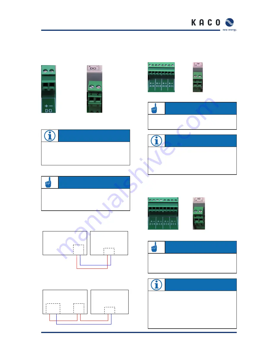
5.4.8 Digital output D0
The digital output can be used as an alarm output to control
signalling devices or as a pulse output to connect a display.
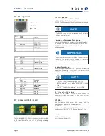
Powador-proLOG M/XL
Powador-proLOG S
Connecting a display to D0
Connecting a signalling device to D0
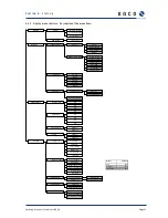
5.4.9 Analogue/digital
inputs
The unit is equipped with four (XL) or one (S, M) analogue
input(s), which are designed for a voltage measurement of 0
to 10 V.
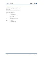
Powador-proLOG XL
Powador-proLOG S
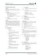
Counter pulses (maximum frequency: 14 Hz) can be recorded
using four (XL) or one (S, M) digital counter input(s). An inter-
face in accordance with the S0 specifi cation must be available.
Powador-proLOG XL
Powador-proLOG S
S e c t i o n 5 ·
I n s t a l l a t i o n
NOTE
To confi gure this function, connect to the Powador-pro-
LOG and make the required settings via -> “Admin moni-
toring > Switching output” in your browser.
ATTENTION
The output is designed as an optocoupler output (N/O
contact) and must therefore be connected to an external
voltage supply, if necessary. The maximum load is 50 mA.
NOTE
The analogue inputs can be optionally converted for
current measurement or resistance measurement.
You do this in the confi guration menu of the Powador-
proLOG (Admin-Messung -> Admin measurement > Ana-
logue channels).
ATTENTION
Incorrect polarity or using an external voltage supply
greater than 24 V can destroy the measuring input. The
24-V supply is available starting at terminal DI+.
ATTENTION
Incorrect polarity or using a voltage supply greater than
12 V can destroy the measuring input.
NOTE
The digital inputs can be optionally converted for status
evaluation.
This means that the Powador-proLOG can evaluate
switching states 0 or 1 (N/C or N/O contact).
This must be set up using the confi guration fi les
for the Powador-proLOG.
Please contact the KACO new energy hotline.
Powador-
pro
LOG
+ -
D0
+ -
24V
+ -
Signalgeber
Powador-proLOG
Impulseingang
Anzeigedisplay
Powador-
pro
LOG
D0
+ -
+ -
Powador-proLOG
Display


