Operating Instructions Powador-proLOG_EN
Page 13
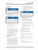
To prevent possible communication faults caused by
electromagnetic radiation, ferrite clips are included
with the Powador-proLOG M. The instal-
lation process is described in 5.4.3
Powador-go (M / XL).
5.4.7 RS485
connection
Use a shielded twisted pair cable to connect
the unit to the RS485 bus (inverter <->
Powador-proLOG). The ports are labelled
“A” and “B”.
The maximum length of the RS485 bus is 1000 m. In practice,
KACO new energy recommends keeping the length to 500 m.
The last bus device must be terminated
with a terminating resistor. The Powador-proLOG is already
terminated at the factory. Each inverter is assigned a separate
address (1 to 32).
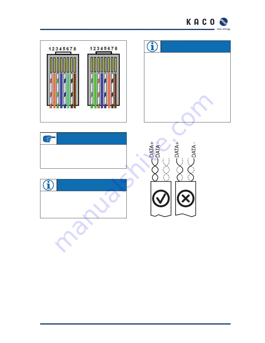
RS485 bus: Assignment of twisted-pair wires
Crossover cable
IMPORTANT
To connect the Powador-proLOG directly to a PC, you
must use a crossover cable (included in the scope of
delivery). If you want to connect it to a switch or hub, you
require a patch cable.
NOTE
–
The designations for A and B vary between manufactur-
ers. Therefore, please pay attention to the designations
Data + and Data -, because only these are defi nitive.
–
A repeater or hub is usually required for cable lengths
greater than 500 m.
–
DC/AC lines and signal lines must be routed separately.
In other words, never install signal lines in the vicinity
of conductors.
–
Only use shielded twisted pair cables.
–
Twisted pair cables feature core pairs that are twisted
together. The same twisted pair must always be used
for both A and B (see image below).
–
Only use cables that conform to the LiYCY specifi cation.
NOTE
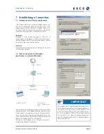
At the factory, the Powador-proLOG is set to use
an IP address of 192.168.100.50 and a netmask of
255.255.255.0.
For detailed instructions on how to set up an Ethernet
connection, see section 7.2.
S e c t i o n 5 ·
I n s t a l l a t i o n


