


Section 3 - 19
K
e
y
C
u
tti
n
g
&
P
in
n
in
g
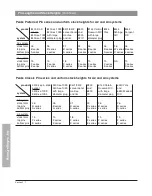
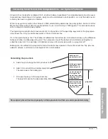
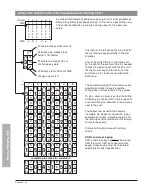
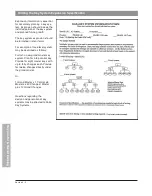
Calculating Small Format Interchangeable Cores A4 Pinning Stacks
plug total
add top pin to
make a stack
total of 14
buildup pin equals
control cut + 6
minus plug total
master pin equals
the deep operating
cut minus the
shallow cut
bottom pin
equals the shallow
operating cut
A4 system has six depths numbered 0 to 5, shallow to deep, respectively. This is a single step progression
system.
Because there is no parity in the A4 system, key interchange between systems in the same keyway
cannot be prevented.
The operating and control shear lines are distinct. All the operating keys work at the operating (plug) shear
line. Only the control key works at the control shear line.
Pin to the operating keys first. The shallow cut determines the bottom pin. A master pin makes up the
difference between shallow and deep operating cuts. The numerical value of the bottom pin and master pin
together is called the “plug total.” For example, a #1 bottom pin plus a #4 master pin results in a plug total
of 5.
Buildup pins are added to the plug total to make the control key operate at the control shear line. Top pins
are added to achieve a uniform pin stack height of 14 in all chambers.
The control dimension, or thickness of the control lug, is a multiple of the increment. The increment is 0.021"
while the control dimension is 0.21". Because the control lug is 6 increment units thick, the control shear line
is 6 units higher than the operating shear line.
Calculating the pin stack
3. Add a top pin to bring the total pin stack to 14.
2. Add 6 to control bitting. Subtract plug total.
The remainder is the buildup pin.
1. Pin operating keys to the plug shear line.
The plug total equals the deep operating bitting.
Non-original pins will not work properly in Kaba products and their use voids product warranty.
Summary of Contents for Peaks Classic
Page 1: ...Technical Manual Preferred Classic ...
Page 3: ...Peaks Preferred Classic Notes ...
Page 4: ...Technical Manual Section 1 Introduction Preferred Classic ...
Page 12: ...Technical Manual Section 2 Product Information Preferred Classic ...
Page 19: ...Section 2 7 Product Information Peaks Preferred Classic Notes ...
Page 41: ...Section 2 30 Product Information Peaks Preferred Classic Notes ...
Page 42: ...Section 2 31 Product Information Peaks Preferred Classic Notes ...
Page 43: ...Section 2 32 Product Information Peaks Preferred Classic Notes ...
Page 44: ...Technical Manual Section 3 Key Cutting and Pinning Preferred Classic ...
Page 66: ...Section 3 22 Key Cutting Pinning Peaks Preferred Classic Notes ...
Page 67: ...Section 3 23 Key Cutting Pinning Peaks Preferred Classic Notes ...
Page 68: ...Preferred Classic Technical Manual Section 4 Key Control Record Keeping ...
Page 79: ...Section 4 11 Key Control Record Keeping Peaks Preferred Classic Notes ...
Page 80: ...Preferred Classic Technical Manual Section 5 Cylinder Installation Guide ...
Page 91: ...Section 5 11 Cylinder Installation Guide Peaks Preferred Classic Notes ...