background image

E37

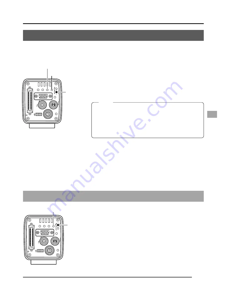
Returning to the REC mode

To return to the REC mode after displaying captured im-
ages, press the MODE button to light up the REC lamp.

SEE INSTRUCTION MANUAL

POWER

DC IN

REMOTE

MONITOR

LENS

FREEZE

PLAY

SET

DOWN

AW/SEL

SEND

SCSI

UP

MENU

MODE

REC

ON 1 2 3 4

MODE

REC lamp

2.

Pressing the SEL button will switch in sequence from
latest image to the previously Stored images.

3.

Images can also be output from memory to an MO/Zip

®

drive or printer.

(


page 38 Saving images from the memory to an MO/Zip

®

 disk )

(


page 39 Outputting images from the memory to a printer )

• It is not possible to enter the PLAY mode directly from the

FREEZE mode. First cancel the freeze before entering the
PLAY mode.

• The character display contents of the monitor screen can

be changed by selecting ON SCREEN in the SYSTEM SET-
TING screen. ( 


Page 59)

Playing back images from the memory

It is possible to play back images stored in the camera’s memory. When in the VGA mode,
images will be displayed in 640 

×

 480 pixels, regardless of whether in the FINE or DRAFT mode.

1.

Press the MODE button to enter the PLAY mode.
The PLAY lamp will light and the latest image stored
will be displayed on the monitor.

 page 10 MODE button)

At this time, the memory image no. will be displayed
at the lower right corner of the screen.

MEMO

SEE INSTRUCTION MANUAL

POWER

DC IN

REMOTE

MONITOR

LENS

FREEZE

PLAY

SET

DOWN

AW/SEL

SEND

SCSI

UP

MENU

MODE

REC

ON 1 2 3 4

SEL

MODE

PLAY lamp

Summary of Contents for KY-F70B

Page 1: ...is made from 100 recycled paper SC96973 002 KY F70B CAMERA DIGITAL C MOUNT For Customer Use Enter below the Serial No which is located on the unit Retain this information for future reference Model No KY F70B Serial No Introduction Before recording Settings and adjustments for recording Basic operations Various recording methods Menu screen settings Connecting to a PC Others ...

Page 2: ...gs must not be blocked or covered The openings should never be blocked by placing the appliance on a bed sofa rug or other similar surface This appliance should never be placed near or over a radiator or heat register This appliance should not be placed in a built in installation such as a bookcase unless proper ventilation is provided 9 This appliance should be operated only from the type of powe...

Page 3: ...as improper adjustment of other controls may result in damage and will often require extensive work by a qualified technician to restore the appliance to normal operation e If the appliance has been dropped or the cabinet has been damaged f When the appliance exhibits a distinct change in performance this indicates a need for service 18 When replacement parts are required be sure the service techn...

Page 4: ...ES SUR SEINE CEDEX FRANCE TEL 33 1 61 04 11 64 5 JVC ESPAÑA S A CTRA GRACIA MANRESA KM 14 750 EDIFICIO CAN CASTANYER 08190 SANT CUGAT DEL VALLES BARCELONA SPAIN TEL 93 5653210 6 JVC BELGIUM S A N V RUE DE LA PETITE LLE 3 KLEIN EILANDSTRAAT BRUXELLES 1070 BRUSSEL BELGIUM TEL 02 529 4211 7 JVC NEDERLAND B V JVC PLEIN DE HEYDERWEG 2 2314 XZ LEIDEN NEDERLAND TEL 071 5453333 8 JVC SVENSKA AB VEDDESTAVA...

Page 5: ...ERLAND TEL 0614051111 12 OY HEDPRO AB LAUTTASAARENTIE 50 FIN 00200 HELSINKI FINLAND TEL 35896828244 13 ELECTROINDUSTRIAL HELLAS S A 62 PIRAEUS AVE 183 46 MOSCHATO ATHENS GREECE TEL 01 4832855 14 ORIELA S A CAMPO STA CLARA 160 A 1100 LISBOA PORTUGAL TEL 351 1 882 3382 15 FACO HF FAXAFEN 12 P O BOX 442 108 108 REYKAJVIK ICELAND TEL 91 588 3050 ...

Page 6: ...ce servicing instructions in the lit erature accompanying the appliance CAUTION TO REDUCE THE RISK OF ELECTRIC SHOCK DO NOT REMOVE COVER OR BACK NO USER SERVICEABLE PARTS INSIDE REFER SERVICING TO QUALIFIED SERVICE PERSONNEL Information for USA This device complies with Part 15 of the FCC Rules Changes or modifications not approved by JVC could void the user s authority to operate the equipment IN...

Page 7: ...ors In order to keep the best performance and furthermore for electromagnetic compatibility we recommend to use cables not exceeding the following length Caution Where there are strong electromagnetic waves or magnetism for example near a radio or TV transmitter transformer motor etc the picture may be disturbed In such case please keep the apparatus away from the sources of the disturbance KY F70...

Page 8: ...drive 20 Connecting a printer 21 Mounting the camera 22 Fall prevention 23 3 Settings and adjustments for recording Setting the dip switches 24 Monitor output settings 24 SCSI ID settings 24 Menu settings 25 VGA mode settings 25 Lens settings 25 Time and date settings 26 Monitor adjustment 28 Focus adjustment 29 White balance adjustment 30 White shading adjustment 32 White spot compensation 34 4 B...

Page 9: ...OCESS 1 3 screen 55 PROCESS 2 3 screen 57 PROCESS 3 3 screen 58 SYSTEM SETTING screen 59 PLAY FREEZE MENU screen 61 REC MENU QUICK screen 62 Resetting settings PLAY FREEZE MENU screen 64 Resetting settings REC MENU screen 65 7 Connecting to a PC Capturing images using the provided software KY SCSI 66 Capturing images using commercially available software 67 Capturing images using the image capture...

Page 10: ... KY SCSI allows connection of a personal computer via SCSI connection for remote control display of preview image and capture of still images Output digital still images to an MO drive Zip drive or compatible printer using SCSI connec tion Remotely control your PC using RS 232C connection software not included Accessories and attachments Battery CR2025 For time and date backup page 16 Replace the ...

Page 11: ...bient temperatures White spots may also appear at a slow shutter speed setting 1 8 s or higher To reduce this phenomenon this product is provided with at built in white spot compensa tion function page 34 Cautionary notes Influence of strong electric waves and magnets Screen noise and discolouration may occur when using the product near antennas of ra dios and televisions or near transformers moni...

Page 12: ...top of the camera Mounting the camera page 22 쐋 Locking screws for the camera mounting bracket M2 6 6mm 3 units CAUTION Always use the attached screws Using screws that exceed 6mm may result in malfunction of the unit 쐏 Screw holes for mounting the camera 1 4 inch Used when mounting the camera to a fixer or rotating platform 쐄 Lithium battery compartment Used to compartment the lithium battery for...

Page 13: ... PLAY SET DOWN AW SEL SEND SCSI UP MENU MODE REC ON 1 2 3 4 While the menu screen is being dis played press this button selected item up While an item is selected use this but ton to change the set value Menu screen flow page 46 쐊 AW SEL DOWN button AW Auto White Press this button to adjust the white bal ance when the light source of the sub ject is changed White balance adjustment page 30 SEL Sel...

Page 14: ...N REMOTE MONITOR LENS FREEZE PLAY SET DOWN AW SEL SEND SCSI UP MENU MODE REC ON 1 2 3 4 Ventilation hole 쐅 REC display lamp This lamp lights when in the REC mode During FREEZE this display lamp will flash During the REC mode camera images are outputted to the MONITOR terminal Pressing the FREEZE button at this time will save the image to the main unit memory Recording images to the main unit memor...

Page 15: ...c in the menu screen Setting the VGA mode page 25 씉 LENS connection terminal Used to connect the lens cable Pin configuration of connectors page 12 Mounting the lens page 17 씊 POWER display lamp This lamp lights when the power of the main unit is on 씋 DC IN power input terminal Mini DIN 8 pin female Main unit power supply DC 12V is sup plied through this terminal For the power supply use the AA P7...

Page 16: ...ve Zo 22 Ω 3 3V p p 4 FLASH 5 SEND 6 RS SDI 7 RS SDO 8 GND 9 12V 10 OPERATION 1 2 8 7 10 6 3 4 5 9 CAUTION Consult your JVC dealer concerning the re mote terminal connection Remote cable must use shielded cable Outer shield of remote cable must to connect 10 pin connector outer metal shell However insert a diode as shown in the dia gram below I O IN 5V CMOS Schmidt Trigger Pull up to 5V at 100k Ω ...

Page 17: ...V p p negative polarity Zo 22 Ω 14 Vs 3 3V p p negative polarity Zo 22 Ω 15 NC SCSI terminal Half pitch 50 pin female Pin no Signal name 1 11 GND 12 GND 13 NC 14 GND 15 25 GND 26 DB 0 27 DB 1 28 DB 2 29 DB 3 30 DB 4 31 DB 5 32 DB 6 33 DB 7 34 DBP 35 GND 36 GND 37 GND 38 TERMPWR input only 39 GND 40 GND 41 ATN 42 GND 43 BSY 44 ACK 45 RST 46 MSG 47 SEL 48 CD 49 REQ 50 I O 1 5 10 6 11 15 1 26 50 25 ...

Page 18: ...the images to an MO disk Zip disk or printer Be sure to terminate the last device on the SCSI bus For the power supply always use the AA P700 AC adapter Connect to the power supply page 18 AC adapter Connect the PC monitor VGA page 19 VGA monitor Connect the MO Zip drive page 20 MO drive or Zip drive Connect the printer page 21 CAUTION Use a 1 2 inch C mount microscope adapter compatible to the us...

Page 19: ...a system to record with this camera using a flash timed by an external freeze switch AC adapter Flash Freeze switch VGA monitor MO drive unit Mount the lens page 17 MEMO Use the following setting for flash connection IRIS MODE MANUAL page 50 WHITE BAL MANUAL page 53 ABL Set in MASTER BLACK page 56 57 Compatible Printer Mitsubishi CP 700DSU E CP 770DW CP 800DW Be sure to terminate the last device o...

Page 20: ...ry is securely in position by the hold ers as shown in the diagram To remove the battery follow the procedure in reverse Screws Battery compartment Holders 1 2 3 4 Replace the cover and retighten the screws Mini screwdriver attached MEMO The time and date will not be displayed correctly when the battery is not installed When replacing the lithium battery reset the time and date Setting the time an...

Page 21: ...tion 햲 First turn the mount clamp ring counterclockwise 1 4 turns with the lens facing you 햳 Slowly turn the lens and after adjusting the position retighten the mount clamp ring 3 Insert the camera cable of the lens into the lens connection terminal on the rear of the main unit then securely lock The iris control is made automatically from the camera When using a manual iris lens set the IRIS MODE...

Page 22: ...mount certainly the provided clamp filter as shown in Figure 2 and 3 on the left Wind the power cable once around the clamp filter Ensure that the clamp filter is mounted as close to the camera as possible as shown in the diagram DC IN POWER DC IN POWER DC IN POWER AC adapter Provided power cable Provided Clamp filter Plug Ring Figure 1 Figure 2 Figure 3 Connect the end with the white marking to t...

Page 23: ...anted electrical waves Commercially available VGA video cable is recommended For the pin assignment see page 13 Pin configuration of connectors Monitor conditions fH 31 47 kHz fV 59 94 Hz Sync signal H V separate TTL negative polarity Dip switch setting page 24 VGA mode set dip switch No 3 to OFF Do not connect the unit to a VGA monitor directly when in the SXGA mode dip switch No 3 ON CAUTION Bef...

Page 24: ...a Zip drive at the same time The image data outputted to an MO Zip drive unit will be 1360 1024 pixels regardless whether the mode is VGA or SXGA or whether the VGA mode is set to FINE or DRAFT The maximum allowed length of the SCSI cable is 3m It is not possible to simultaneously output the image data to a printer and MO Zip drive The image data will be save as uncompressed TIF files one file app...

Page 25: ...ID is required It is not possible to simultaneously output the image data to a printer and MO Zip drive SEE INSTRUCTION MANUAL POWER DC IN REMOTE MONITOR LENS FREEZE PLAY SET DOWN AW SEL SEND SCSI UP MENU MODE REC ON 1 2 3 4 POWER ALARM SHEET PAPER DATA OPEN CP700DSA MITSUBISHI ONLINE COPY CUT PAPER FEED ON 1 2 3 4 ID 7 Set the ID of the printer side to other than 7 Dip switches SCSI terminal CAUT...

Page 26: ... falling and securely mount the unit Changing the camera mounting bracket position Mounting method Rotation prevention hole Camera mounting screw hole Camera mounting bracket When shipped the camera mounting bracket is mounted on the bottom of the unit To mount it on the top of the unit simply remove the 3 locking screws holding the camera mounting bracket CAUTION Always use the attached screws Us...

Page 27: ...stal lation Falling of the unit may result in bodily injury To prevent the unit from falling connect the unit to a strong surface with a wire chain etc When connecting such chain use the bracket locking screw hole on the side which the camera mounting bracket is not mounted M2 6 6mm Take special caution to the length of the optional wire as well For the fall preventive wire use the one with the st...

Page 28: ...ard SCSI ID settings DiP switches 1 and 2 are set depending on the used system to set the SCSI ID Default ID 7 Set when connecting a printer or MO drive unit directly to the main unit When making this setting the main unit will become the initia tor Set when exporting images to a PC Make sure that the ID numbers of the connecting devices are not the same When making this setting the PC will become...

Page 29: ... lens in MANUAL or no lens Default setting AUTO Menu settings The settings for the VGA mode and lens are made on the menu screen The menu screen is outputted through the VGA monitor EXPOSURE I R I S MODE AUTO NORM 1 AL 0 0 FULL STEP 1 8 s P STE I SO 4 0 0 I SO I R I S LEVEL 0 AE LEVEL I R I S DETECT I TY I R I S AREA SHUTTER SPEED LEVEL SENS I T I V ALC MAX ET T I NG SYSTEM S ON SCREEN FRZ D I SPL...

Page 30: ... button to display the TIME AD JUST screen Time and date settings 3 Settings and adjustments for recording continued SEE INSTRUCTION MANUAL POWER DC IN REMOTE MONITOR LENS FREEZE PLAY SET DOWN AW SEL SEND SCSI UP MENU MODE REC ON 1 2 3 4 UP DOWN MODE SET REC lamp MENU REC MENU screen REC MENU 1 EXPOSURE Purple 2 WH I TE BALANCE 3 FREEZE 4 PROCESS 5 SYSTEM SETT I NG ETT I NG SYSTEM S ON SCREEN FRZ ...

Page 31: ... will display 00 The clock will start when the 00 is displayed in purple and the SET button is pressed Press the SET button when the actual time reaches 00 seconds 7 OK will be displayed for approximately 3 seconds and the unit will return to the SYSTEN SETTING screen 8 Press the MENU button twice to return to the normal screen MEMO When setting the time and date always set the seconds 00 Pressing...

Page 32: ...For adjustment of the monitor see the instruction manual of the monitor The default value of the peak level is set to 0 7 V To change the setting to 0 58V select BAR LEVEL in the SYSTEM SET TING screen Page 60 It is not possible to switch between the REC PLAY modes while the colour bar is displayed Image data cannot be output to an MO Zip drive printer or PC while the colour bar is displayed Dip s...

Page 33: ... will be displayed in purple 3 Press the UP or DOWN button to select the SHUTTER item to STEP then press the SET button By way of confirmation The STEP display will become white 4 Press the DOWN button to select SHUTTER SPEED then press the SET button The set value of SHUTTER SPEED will be displayed in purple 5 Press the UP or DOWN button to select the value to 1 30 s then press the SET button By ...

Page 34: ...ending on the usage environment 3200K when using low temperature lighting such as a halogen lamp etc 5200K when using high temperature lighting under the sunlight etc Pressing the SET button will register the setting in the main unit memory The set value will be displayed in white MEMO Pressing the MENU button without pressing the SET button will not register the set value and the unit will return...

Page 35: ...t to a slow shutter speed the white bal ance operation may take some time before completion With the factory setting it may take up to 13 seconds de pending on the subject When setting the shutter speed to 1 s takes maximum of 1 minute 45 seconds 7 Press the AW Auto White button When auto white is in operation the auto white op eration area and AUTO WHITE OPERATION will be displayed on the monitor...

Page 36: ...10 MODE button If the button is pressed for less than 2 seconds the REC MENU QUICK screen will appear Page 49 2 Press the UP or DOWN button select 2 WHITE BAL ANCE the text will be displayed in purple when se lected then press the SET button The WHITE BALANCE screen will appear 3 Press the UP DOWN and SET buttons to set SHAD ING MODE in the WHITE BALANCE screen to ADJUST 4 Use the UP or DOWN butto...

Page 37: ...ite balance adjustment page 30 White balance adjustment CE WHI TE BALAN COLOR TEMP WH I TE BAL AUTO 0 3 2 0 0K ADJU Purple ST 0 0 0 0 LEVEL R LEVEL B LEVEL R LEVEL G LEVEL B MODE SH ADING WHITE BALANCE screen 3 Pressing the MENU button without pressing SET will return the setting to the original values without registering to the memory MEMO WHITE BALANCE screen 4 WHITE BALANCE screen 5 CE WHI TE B...

Page 38: ...s the UP or DOWN but ton to select 4 PROCESS the text will be displayed in purple when selected and then press the SET button The PROCESS screen will appear 5 Press the UP or DOWN button to select the PIXEL CHECK in the PROCESS 2 3 screen When the SET button is pressed the PIXEL CHECK screen appears 6 When the SET button is pressed detection of the posi tions of white spots start The detection may...

Page 39: ...ght enters the CCD while white spot detection is being performed or due to the con ditions of the white spots In this case confirm that light is not entering the CCD If light is not entering the CCD but the screen nevertheless remain displayed accelerate the shutter one step and perform the detection again When white spot compensation is carried out the compensation of the pixel data is performed ...

Page 40: ...n MEMO The unit will automatically enter the REC mode when the power is turned on 2 Press the FREEZE button An image output via the MONITOR terminal will be grabbed and stored in the camera s memory At this time the REC LED will flash and FREEZE will appear on the screen To stop this message appearing set FRZ DISPLAY to OFF page 59 3 Cancel FREEZE Press the FREEZE button a second time to cancel th...

Page 41: ...from the FREEZE mode First cancel the freeze before entering the PLAY mode The character display contents of the monitor screen can be changed by selecting ON SCREEN in the SYSTEM SET TING screen Page 59 Playing back images from the memory It is possible to play back images stored in the camera s memory When in the VGA mode images will be displayed in 640 480 pixels regardless of whether in the FI...

Page 42: ...e of the following error messages will appear for approxi mately 3 seconds ERROR SCSI check the cable ERROR WRITE write error ERROR FORMAT format the disk ERROR DISKFULL disk is full ERROR DIRECTRYFULL directory error ERROR READ read error ERROR MO Other MO error ERROR ZIP Other ZIP error BUFFER IS FULL When sending more than 32 images no 33 and after will be displayed ALL VIDEO MEMORY IS FULL Whe...

Page 43: ...data is not successfully outputted to the printer one of the following error messages will appear for approxi mately 3 seconds ERROR SCSI check the cable ERROR PRINTER printer error PR I N O K T OUT Print completed Print confirmation MEMO Do not turn off the power of the main unit or other connected devices when the SCSI output mark is displayed Set the SCSI ID of the MO Zip drive or printer to ot...

Page 44: ...ssing the MENU button in the FREEZE screen of the REC mode will also display the PLAY FREEZE MENU screen MEMO O ME V I DE MO O K RY LEAR C Memory cleared 3 Pressing the SET button will clear the memory of the stored contents When completed VIDEO MEMORY CLEAR OK will ap pear for approximately 3 seconds and the normal screen will return in the case of the FREEZE condition MEMO PLAY FREEZE mode menu ...

Page 45: ... UP or DOWN button to select VIDEO MEMORY CLEAR then press the SET button to dis play the VIDEO MEMORY CLEAR screen MEMO To cancel press the MENU button to return to the MENU screen without clearing the images O ME V I DE MO O K RY LEAR C Memory cleared 4 Pressing the SET button will clear the memory of the stored contents When completed VIDEO MEMORY CLEAR OK will ap pear for approximately 3 secon...

Page 46: ... SET button 5 Press either UP or DOWN to change the shutter speed When a black bar can be seen on the screen decrease the shutter speed by pressing the DOWN button When a white bar can be seen on the screen increase the shutter speed by pressing the UP button 6 Press the SET button when the bar is at its minimum Data is registered to the main unit memory MEMO Pressing the MENU button without press...

Page 47: ...the value to ON The outputted image will be the negative image 5 Pressing the SET button will register the setting to the memory 6 Press the MENU button twice to return to the normal screen Outputting negative images SEE INSTRUCTION MANUAL POWER DC IN REMOTE MONITOR LENS FREEZE PLAY SET DOWN AW SEL SEND SCSI UP MENU MODE REC ON 1 2 3 4 UP DOWN MODE SET REC lamp MENU ETT I NG SYSTEM S ON SCREEN FRZ...

Page 48: ...output from FREEZE input depends on the timing of the FREEZE input and shutter speed In addition the pulse length of the flash output differs depending on the shutter speed Since the diagram below is the timing chart when in the SXGA mode CCD OUT and MONI TOR OUT are synchronous However the timing of MONITOR OUT will be asynchronous with CCD OUT when in the VGA mode and there will also be no WEN o...

Page 49: ... Even in the SXGA mode the FREEZE input interval is restricted as shown in Table B Do not input at a shorter interval than the minimum interval shown in the table A B 1 15s 1 8s 1 60s 1 30s 1 250s 1 125s 1 1000s 1 2000s 1 500s 337 395 287 304 277 278 277 277 277 0 203 0 063 0 203 0 063 0 203 0 063 0 203 0 063 2 953 0 063 0 203 0 063 5 953 0 063 6 453 0 063 4 953 0 063 MEMO If the shutter mode is s...

Page 50: ...PLAY FREEZE MENU screen REC MENU QUICK screen and REC MENU screen MEMO Pressing the MENU button while in any of the menu screens will return the unit to the previous screen Press the MENU button for more than 2 seconds while in the REC mode will display not the REC quick menu but the REC normal menu screen The MENU RESET screen VIDEO MEMORY CLEAR screen TIME ADJUST screen can all be accessed from ...

Page 51: ... DEP ETT I NG SYSTEM S ON SCREEN FRZ D I SPLAY ITY F I NE MEMORY NUM 0 7V OFF R CLEA PR IOR MON I T NARROW AREA OR MORY BAR LEVEL NEGA MENU RE I T ME ADJUST S V I DEO ME ET OFF SYNC ON G ON D I SK REC normal menu screen EXPOSURE screen WHITE BALANCE screen FREEZE screen PROCESS screen SYSTEM SETTING screen Normal screen Press the MENU button for at least 2 seconds while in the REC mode When a remo...

Page 52: ...SET button The setting will be confirmed and registered to the memory The set value will be displayed in purple indicating that it can be changed 4 Use the UP and DOWN buttons to change to set value then press the SET button to confirm the set value will return to white MEMO Continuous pressing of the UP or DOWN button will change the set value in increment of 10 Use this feature when mak ing larg...

Page 53: ...utton to display the REC quick menu screen If the MENU button is pressed for more than 2 sec onds the REC normal menu will appear In this case press the MENU button once to return to the normal screen then press the MENU lightly page 10 MODE button 2 5 Follow the steps described in the REC normal screen menu REC MENU QU I CK I R I S LEVEL SHUTTER AE LEVEL STEP 0 1 8 s STEP LEVEL SENS I T I V I TY ...

Page 54: ...t the submenu screens of the REC MENU Menu item IRIS MODE AE LEVEL IRIS LEVEL Default value AUTO 0 128 1 EXPOSURE Used for video level related settings such as iris shutter sensitivity etc page 50 2 WHITE BALANCE Used to make settings for colour temperature white balance shad ing compensation etc page 53 3 FREEZE Used to set the cancel method when using the FREEZE function page 55 4 PROCESS 1 3 Us...

Page 55: ...camera to that of the monitor The shutter can be changed in detail using the SPEED submenu item Page 42 Recording a PC monitor RANDOM Used to synchronize the CCD accumulation tim ing with the FREEZE input page 45 The shutter speed can be changed using the SPEED submenu item EEI Used to automatically change the shutter speed depending on the object brightness max 1 2384 7s OFF 1 30 s when VGA is se...

Page 56: ...i cally switches the sensitivity depending on the brightness Variable range ISO200 ISO400 Menu item SHUTTER SPEED SENSITIVITY LEVEL ALC MAX 6 Menu screen settings continued EXPOSURE screen continued Default value STEP 1 8 s V SCAN 1 30 s RANDOM 1 125 s STEP STEP ISO100 V SENS ISO100 ISO400 MEMO When the shutter speed is slower than 1 4 s 1 15 s in the VGA DRAFT mode the screen update rate becomes ...

Page 57: ...justment can be made for the white balanced using LEVEL R and LEVEL B MANUAL the white balance can be changed using LEVEL R and LEVEL B The colour red of the white balance can be adjusted when WHITE BAL is set to AUTO or MANUAL Increase the number deeper reds on the screen Decrease the number paler reds on the screen Variable range during AUTO 32 31 Variable range during MANUAL 0 255 The colour bl...

Page 58: ...sted only when SHADING MODE is set to ADJUST Increase the number paler green at the bottom of the screen and deeper green at the top Decrease the number paler green at the top of the screen and deeper green at the bottom Variable range 128 127 The colour blue of the white shading is adjusted only when SHADING MODE is set to ADJUST Increase the number paler blue at the bottom of the screen and deep...

Page 59: ...etails ADJUST changes the detail emphasis OFF no detail emphasis The emphasis level of the detail is adjusted when DETAIL is set to ADJUST Sharpen the detail increase the number Soften the detail decease the number Variable range 7 7 Adjusted when you want to reduce noise in black areas Noise in black areas is reduced because the frequency characteristics of areas where the image signal level fall...

Page 60: ... to reduce noise in the video signal OFF Noise reduction is not performed LOW MIDDLE HIGH Noise reduction is performed Amount of reduction is increased in the order of LOW MIDDLE HIGH Used to adjust the pedestal level master black which is normally set to zero which is the standard black of the capped lens To see more detail in black area increase the pedestal level which brightens the entire scre...

Page 61: ...ther to automatically adjust the black level of the video when recording Adjust when the black level of the video during recording fluctuates NORMAL executes ABL Auto Black Level adjustment using a fixed value ADJUST the compensation of the ABL adjustment can be changed using the LEVEL submenu item below The black level can be adjusted only when ABL is set to ADJUST Decrease the black level higher...

Page 62: ... with this setting Used to adjust the R G signal 0 25 Variable range 0 31 Used to adjust the R B signal 0 25 Variable range 0 31 Used to adjust the G R signal 0 25 Variable range 0 31 Used to adjust the G R signal 0 25 Variable range 0 31 Used to adjust the G B signal 0 25 Variable range 0 31 Used to adjust the G B signal 0 25 Variable range 0 31 Used to adjust the B R signal 0 25 Variable range 0...

Page 63: ... is given to the MO or Zip drive Use to set the resolution of the image displayed on the monitor in the VGA mode FINE 640 480 pixels the image is updated 7 5 times per second DRAFT 640 240 pixels however the image is updated 30 times per second SYSTEM SETTING screen MEMO is shown in cases when ALC EEI and AUTO IRIS all fail to function MEMO This menu item cannot be selected when the unit is set th...

Page 64: ... superimposed 6 Menu screen settings continued SYSTEM SETTING screen continued MEMO When set to FULL the display of the image at the time of FREEZE is delayed Also diagonal lines in the monitor image may appear jagged No matter which setting is selected the resolution of the actual recorded image remains unchanged at 1360 1024 MEMO MENU RESET does not return this setting to default value Even when...

Page 65: ...sed to set which device has output priority when both printer and MO or Zip drive are connected PRINTER output priority is given to the printer MO output priority is given to the MO or Zip drive Used to set the level of the colour bar signal outputted from the MONITOR terminal of this unit 0 7V outputs 0 7V colour bar signals 0 58V outputs 0 58V colour bar signals Default value MEMORY NUM DISK 0 7...

Page 66: ...D accumulation timing with the FREEZE input page 45 The shutter speed can be changed using the SPEED submenu item EEI Used to automatically change the shutter speed depending on the object brightness max 1 2384 7 s OFF 1 30 s when VGA is set to the DRAFT mode 1 7 5 s when VGA is set to the FINE mode 1 7 5 s when in the SXGA mode The shutter sped can be changed when the shutter is set to STEP V SCA...

Page 67: ...o the printer DISK output priority is given to the MO or Zip drive Default value STEP STEP ISO100 V SENS ISO100 ISO400 DISK MEMO When the shutter speed is slower than 1 4 s 1 15 s in the VGA DRAFT mode the screen update rate becomes longer in correspondence with the shutter speed and time will be required for the following operations Auto white auto iris ALC If the shutter speed is set at 1 4 s or...

Page 68: ...SET button to initialize all settings other than the values set in the TIME ADJUST screen and SYNC ON G item 4 At this time a MENU RESET OK message will appear for 3 seconds then the unit will return to the PLAY FREEZE menu screen 5 Press the MENU button once more to return to the nor mal screen SEE INSTRUCTION MANUAL POWER DC IN REMOTE MONITOR LENS FREEZE PLAY SET DOWN AW SEL SEND SCSI UP MENU MO...

Page 69: ...settings other than the values set in the TIME ADJUST screen and SYNC ON G item 5 At this time a MENU RESET OK message will appear for 3 seconds then the unit will return to the SYSTEM SETTING screen 6 Press the MENU button twice to return to the normal screen SEE INSTRUCTION MANUAL POWER DC IN REMOTE MONITOR LENS FREEZE PLAY SET DOWN AW SEL SEND SCSI UP MENU MODE REC ON 1 2 3 4 UP DOWN MODE SET R...

Page 70: ...using a one to one connection Correct operation may be impeded if connected with other equipment in a daisy chain To use other SCSI equipment at the same time use a separate SCSI board Set the SCSI ID to a number other than that of the SCSI board other than 7 Set the monitor output mode to the SXGA mode page 24 For details read the Readme txt file on the floppy disk AC ADAPTER AA P700 ON OFF POWER...

Page 71: ... if other software than Adobe Photoshop 5 0 5 5 is used Capturing images using commercially available software Adobe Photoshop Photoshop LE etc are commercially available graphic software applica tions for capturing images The provided TWAIN driver is used for capturing images When con necting the hardware you will have to purchase a separate SCSI board and SCSI cable PC operating system Windows 9...

Page 72: ... continued MEMO To display the entire image 1360 1024 pixels of the camera s output video on the PC monitor the PC s video circuit and the PC monitor s resolution must be higher than this 1600 1200 pixels etc In this system use with the camera set to the SXGA mode page 24 Also refer to the instruction manual for the capture board AC adapter Capture board Matrox Meteor 2 MC 4 PC Microscope adapter ...

Page 73: ...the following timing diagram for the setting of the capture board Video signal Sync signal A Front porch B Synch signal width C Back porch D Blanking time E Video signal interval F Cycle No of bits No of lines Dot clock 14 31818 MHz Horizontal frequency 8 00 kHz Vertical frequency 7 49 Hz H V Capturing images using the image capture board continued E D F A C B ...

Page 74: ...the signal level is adjusted in the range of 2 graduations of the aperture under dark lighting and 8 graduations when in FINE under bright lighting 6 graduations in DRAFT When the IRIS mode is set to manual the sensitivity and electronic shutter change continuously whilst the iris setting stays fixed page 50 IRIS MODE This feature holds the advantage of being able to record under changing light co...

Page 75: ... polarity or SYNC ON GREEN 0 3V p p SCSI output SCSI 2 50 pin half pitch SCSI connector Output modes Can switch between target and initiator Built in framestore capacity 5 incompressed images at SXGA resolution or 4 when output signal is a Operating temperature range 0 C to 40 C with humidity of less than 80 RH Input voltage DC 12V Power consumption Max 15W Mass Approx 850g Item When using KY SCSI...

Page 76: ... 70 80 88 Design and specifications are subject to change without notice 1 4 inch screw Windows is a registered trademark Microsoft Corporation of America and others Other company names and product names are trademark or registered trademark of their respective owners Specifications ...

Page 77: ...le Kamera KY F70B BEDIENUNGSANLEITUNG Einleitung Vor der Aufnahme Einstellungen für die Aufnahme Grundbetrieb Verschiedene Aufnahmemethoden Menübildschirm Einstellungen Anschließen an einen Computer Sonstiges ...

Page 78: ...U VERMEIDEN Dieses Gerät sollte nur mit 12 V Gleichstrom verwendet werden ACHTUNG Verwenden Sie zur Vermeidung von elektrischem Schlag und Feuer keine andere Stromversorgung Änderungen der in dieser Bedienungsanleitung gegebenen Daten auf Grund von Entwurfsänderungen bleiben jederzeit vorbehalten ACHTUNG Öffnen Sie das Gehäuse nicht um die Gefahr von elektrischem Schlag zu vermeiden Im Inneren sin...

Page 79: ...ild gestört werden In solch einem Fall das Gerät von der Störquelle entfernt halten KY F70B ist bei Verwendung in einem Krankenhaus oder einer anderen medizinischen Umgebung für den Betrieb mit nicht mit den Patienten zusamenhängender Ausrüstung entworfen KY 70B und AA P700EG haben die Prüfung entsprechend der IEC Sicherheitsnorm 601 1 bestanden Die Verwendung von Zubehör das nicht den Sicherheits...

Page 80: ...nschließen an einen Drucker 21 Anbringen der Kamera 22 Verhütung von Herunterfallen 23 3 Einstellungen für die Aufnahme DIP Schaltereinstellung 24 Monitor Ausgangseinstellungen 24 SCSI ID Einstellungen 24 Menüeinstellungen 25 Einstellung des VGA Modus 25 Objektiveinstellungen 25 Einstellung von Zeit und Datum 26 Monitoreinstellung 28 Fokussieren 29 Weißabgleich 30 Weißwert Korrektur 32 Weißpunktau...

Page 81: ... 6 Menübildschirm Einstellungen Menübildschirm Ablauf 46 Einstellverfahren 48 Zu den Untermenü Bildschirmen des Bildschirms REC MENU 50 Bildschirm EXPOSURE 50 Bildschirm WHITE BALANCE 53 Bildschirm FREEZE 55 Bildschirm PROCESS 1 3 55 Bildschirm PROCESS 2 3 57 Bildschirm PROCESS 3 3 58 Bildschirm SYSTEM SETTING 59 Bildschirm PLAY FREEZE 61 Bildschirm REC MENU QUICK 62 Rückstellen von Einstellungen ...

Page 82: ...SCSI Anschluß für Fernsteuerung Anzeige von Vorschaubildern und Einfangen von Standbildern Ausgabe von digitalen Standbildern zu einem MO Laufwerk einem Zip Laufwerk oder einem kompatiblen Drucker unter Verwendung des SCSI Anschlusses Fernsteuerung Ihres Computers über den RS 232C Anschluß Software nicht mitgeliefert Zubehör und Zusatzgeräte Batterie CR2025 Für Netzausfallschutz für Zeit und Datum...

Page 83: ...it 1 8 s oder länger auftreten Zur Verringerung dieser Erscheinung hat dieses Erzeugnis eine eingebaute Funktion zum Ausgleich von weißen Punkten Seite 34 Vorsichtshinweise Einfluß von starken elektrischen Wellen oder Magnetismus Bei Verwendung des Erzeugnisses in der Nähe von Radio oder Fernsehantennen oder in der Nähe von Transformatoren Monitoren usw mit einem starken Magnetfeld kann es auf dem...

Page 84: ...ng M2 6 6 mm 3 Stück ACHTUNG Unbedingt die mitgelieferten Schrauben verwenden Verwendung von Schrauben mit einer Länge von mehr als 6 mm kann Fehlfunktion des Gerätes verursachen 쐏 Gewindelöcher für Anbringen der Kamera 1 4 Zoll Für Anbringen der Kamera an einer Einspannvorrichtung oder einem Drehkopf 쐄 Lithium Batteriefach Für Aufnahme der Lithium Batterie zum Schutz von Datum und Zeit bei Netzau...

Page 85: ...peicherte Bilder wiedergibt Wiedergabe von gespeicherten Bildern Seite 37 DOWN Wenn diese Taste gedrückt wird während der Menübildschirm angezeigt wird so wird der im Menü gewählte Punkt nach unten bewegt Bei gewähltem Punkt dient diese Taste zum Ändern des Einstellwertes Menübildschirm Ablauf Seite 46 쐂 Taste MENU Drücken Sie diese Taste um den Menübildschirm vom Anschluß MONITOR auszugeben Drück...

Page 86: ...ONITOR LENS FREEZE PLAY SET DOWN AW SEL SEND SCSI UP MENU MODE REC ON 1 2 3 4 Ventilationsöffnung Einstellungen am Menübildschirm Seite 46 쐅 Anzeigelampe REC Diese Lampe leuchtet im Aufnahmemodus REC Während Standbild FREEZE blinkt diese Lampe Im Aufnahmemodus REC werden Kamerabilder zum Anschluß Monitor abgegeben Durch Druck auf die Taste FREEZE zu dieser Zeit wird das Bild im Speicher der Haupte...

Page 87: ...eite 24 Anschließen an einen Computer Seite 66 쐉 Taste FREEZE Drücken Sie diese Taste inAufnahmemodus REC um ein Standbild des am Anschluß M O N I TO R a b g e g e b e n e n B i l d e s einzufangen Gleichzeitig wird das Standbild im Speicher der Haupteinheit gespeichert Durch erneuten Druck auf diese Taste wird die Standbildfunktion ausgeschaltet und zum Kamerabild zurückgekehrt Speichern von Bild...

Page 88: ...chirmtes Kabel verwendet werden Die äußere Abschirmung des Fernbedienungskabels muß an die äußere Metallhülle des 10 stiftigen Anschlusses angeschlossen werden Klemmenname FREEZE WEN FLASH I O IN 5V CMOS Schmitt Trigger Anheben zu 5 V durch 100 kΩ OUT 3 3 V p p negative Polarität OUT Offener Kollektor Stift Nr Signalname 1 A WHITE L aktiv Zi 22 kΩ 2 FREEZE L aktiv Zi 100 kΩ 3 WEN L aktiv Zo 22 Ω 3...

Page 89: ...negative Polarität Zo 22 Ω 14 Vs 3 3 V p p negative Polarität Zo 22 Ω 15 NC SCSI Anschluß 50 stiftige Buchse mit halber Teilung Stift Nr Signalname 1 11 GND 12 GND 13 NC 14 GND 15 25 GND 26 DB 0 27 DB 1 28 DB 2 29 DB 3 30 DB 4 31 DB 5 32 DB 6 33 DB 7 34 DBP 35 GND 36 GND 37 GND 38 TERMPWR nur Eingang 39 GND 40 GND 41 ATN 42 GND 43 BSY 44 ACK 45 RST 46 MSG 47 SEL 48 CD 49 REQ 50 I O 1 26 50 25 1 5 ...

Page 90: ... SCSI Kette muß mit einem Abschlußwiderstand versehen werden Verwenden Sie für die Stromversorgung immer das Netzgerät AA P700 An die Stromversorgung anschließen Seite 18 Netzgerät Mikroskopadapter Den PC Monitor anschließen VGA Seite 19 VGA Monitor Das MO Zip Laufwerk anschileßen Seite 20 MO Laufwerk oder Zip Laufwerk Den Drucker anschließen Seite 21 4 mm oder weniger ACHTUNG Verwenden Sie einen ...

Page 91: ...cht Standbildschalter VGA Monitor MO Laufwerk MEMO Verwenden Sie die folgende Einstellung für Blitzanschluß IRIS MODE MANUAL Seite 50 WHITE BAL MANUAL Seite 53 ABL Auf MASTER BLACK stellen Seite 56 57 AC ADAPTER AA P700 ON OFF POWER POWER ALARM SHEET PAPER DATA OPEN CP700DSA MITSUBISHI ONLINE COPY AA P700 AC100V MONITOR SCSI REMOTE DC IN KY F70B CAMERA DIGITAL C MOUNT CUT PAPER FEED Das letzte Ger...

Page 92: ...TY Dies ist keine Fehlfunktion Wenn diese Meldung weiterhin auch nach einem zweiten Einschalten erscheint so wenden Sie sich an Ihren JVC Händler Die Meldung BATTERY EMPTY erscheint nicht wenn die Stromversorgung direkt nach dem Ausschalten des Gerätes eingeschaltet wird Warten Sie mindestens 20 Sekunden bevor Sie die Stromversorgung wieder einschalten Entfernen Sie die zwei Schrauben mit dem mitg...

Page 93: ...ektivanschluß auf der Rückseite der Haupteinheit an und verriegeln Sie es Die Blende wird automatisch durch die Kamera gesteuert Stellen Sie bei Verwendung eines Objektivs mit manueller Blende den Blendenmodus IRIS MODE auf MANUAL Seite 50 4 Schließen Sie bei Verwendung einer Objektivfernsteuerung das Objektivsteuerkabel Buchse an die Fernsteuerung an Stellen Sie IRIS MODE auf MANUAL wenn die Obje...

Page 94: ... die weiße Anzeige des Netzkabels zur Seite der AA P700 kommt Um ungewünschte elektrische Wellen auf ein Mini mum zu bringen den mitgelieferten Klemmfilter wie in Abb 2 und 3 auf der linken Seite gezeigt sicher anbringen Das Netzkabels einmal um den Klemmfilter wickeln Sicherstellen daß der Klemmfilter wie in der Abbildung gezeigt so nahe wie möglich an der Kamera angebracht ist Das Ende mit der w...

Page 95: ...in handelsübliches VGA Videokabel wird empfohlen Beziehen Sie sich für die Stiftbelegung auf Seite 13 Stiftbelegung der Anschlüsse Monitorbedingungen fH 31 47 kHz fV 59 94 Hz Synchronisationssignal H V separat TTL negative Polarität DIP Schaltereinstellung Seite 24 VGA Modus DIP Schalter Nr 3 auf OFF stellen Das Gerät nicht direkt an einen VGA Monitor anschließen wenn es im SXGA Modus ist DIP Scha...

Page 96: ...omversorgung der Kamera nach dem Einschalten der Stromversorgung für das MO Zip Laufwerk ein Schalten Sie beim Ausschalten der Stromversorgung für das MO Zip Laufwerk die Stromversorgung der Kamera aus und wieder ein Verwenden Sie eine für DOS formatierte Es ist auch nicht möglich gleichzeitig ein MO Laufwerk und ein Zip Laufwerk anzuschließen Die zu einem MO Zip Laufwerk ausgegebenen Bilddaten ha...

Page 97: ...r Druckern ist nicht möglich Die zu einem Drucker ausgegebenen Bilddaten haben 1360 1024 Pixel unabhängig davon ob VGA oder SXGA Modus verwendet wird oder ob der VGA Modus auf FINE Fein oder DRAFT Grob eingestellt ist Die maximal zulässige Länge für das SCSI Kabel ist 3 m Beim Anschluß eines MO Zip Laufwerks an einen Computer ist separate Einstellung der SCSI ID erforderlich Es ist nicht möglich d...

Page 98: ...alterung Anbringungsmethode KY F70B CAMERA DIGITAL C MOUNT Loch zur Verhütung von Verdrehen Stativgewinde Kamerahalterung Beim Versand ist die Kamerahalterung an der Unterseite des Gerätes angebracht Entfernen Sie einfach die drei Halteschrauben der Kamerahalterung wenn die Kamerahalterung an der Oberseite des Gerätes angebracht werden soll ACHTUNG Unbedingt die mitgelieferten Schrauben verwenden ...

Page 99: ...uchen Ein Herabfallen des Gerätes kann Körperverletzungen verursachen Verbinden Sie das Gerät zum Verhüten von Herunterfallen mit einem Drahtseil usw mit einer festen Oberfläche Verwenden Sie zum Anschließen eines solchen Drahtseils eins der Halterungsschraubenlöcher auf der Seite auf der die Halterung nicht angebracht ist M2 6 6 mm Auch besonders auf die Länge der optionalen Drähte achten Verwend...

Page 100: ...rd Die DIP Schalter Nr 1 und 2 werden entsprechend dem verwendeten System zur Einstellung der SCSI ID verwendet Vorgabe ID 7 Bei direktem Anschluß eines Druckers oder eines MO Laufwerks an die Haupteinheit einstellen Wenn diese Einstellung gemacht wird wird das Hauptgerät zum Initiator Bei Export von Bildern zu einem Computer einstellen Stellen Sie sicher daß alle angeschlossenen Geräte verschiede...

Page 101: ...er Blende in manuellem Betrieb oder keines Objektivs einstellen Vorgabeeinstellung AUTO Menüeinstellungen Die Einstellungen für VGA Modus und Objektiv werden vom Menübildschirm her durchgeführt Der Menübildschirm wird über den VGA Monitor ausgegeben EXPOSURE I R I S MODE AUTO NORM 1 AL 0 0 FULL STEP 1 8 s P STE I SO 4 0 0 I SO I R I S LEVEL 0 AE LEVEL I R I S DETECT I TY I R I S AREA SHUTTER SPEED...

Page 102: ...rm TIME ADJUST anzuzeigen Einstellung von Zeit und Datum 3 Einstellungen für die Aufnahme fortgesetzt ETT I NG SYSTEM S ON SCREEN FRZ D I SPLAY I TY ON F I NE D I SK MEMORY NUM 0 7V OFF R CLEA PR IOR MON I TOR OFF SYNC G ON NARROW AREA MORY BAR LEVEL NEGA MENU RE I T ME ADJUST S V I DEO ME ET Purple SEE INSTRUCTION MANUAL POWER DC IN REMOTE MONITOR LENS FREEZE PLAY SET DOWN AW SEL SEND SCSI UP MEN...

Page 103: ...ekundenanzeige zeigt 00 an Die Uhr beginnt zu laufen wenn 00 purpurfarbig angezeigt wird und die Taste SET gedrückt wird Drücken Sie die Taste SET wenn die tatsächliche Zeit 00 Sekunden ist 7 OK wird etwa 3 Sekunden lang angezeigt und die Anzeige kehrt zum Bildschirm SYSTEM SETTING zurück 8 Drücken Sie die Taste MENU zweimal um zum normalen Bildschirm zurückzukehren MEMO Stellen Sie bei der Einste...

Page 104: ...e den VGA Monitor an den Anschluß MONITOR an 3 Stellen Sie den DIP Schalter 4 an der Rückseite der Kamera auf ON 4 Schalten Sie die Stromversorgung der Kamera ein 5 Stellen Sie den VGA monitor ein MEMO Beziehen Sie sich für die Einstellmethode für den Monitor auf die Bedienungsanleitung für den Videomonitor Der Vorgabewert für den Spitzenpegel ist auf 0 7 V eingestellt worden Wählen Sie zur Änderu...

Page 105: ...dschirm REC MENU QUICK anzuzeigen Seite 60 10 Taste MODE SET 2 Drücken Sie die Taste UP oder DOWN um SHUTTER zu wählen und drücken Sie dann die Taste SET Der Einstellwert für SHUTTER wird purpurfarbig angezeigt 3 Drücken Sie die Taste UP bzw DOWN um STEP für den Punkt SHUTTER zu wählen und drücken Sie dann die Taste SET Als Bestätigung wird der Punkt STEP weiß angezeigt 4 Drücken Sie die Taste UP ...

Page 106: ...K Bei Verwendung von Beleuchtung mit niedriger Farbtemperatur z B eine Halogenlampe usw 5200 K Bei Verwendung von Hochtemperaturbeleuchtung unter Sonnenlicht usw Durch Druck auf die Taste SET wird die Einstellung im Speicher der Haupteinheit gespeichert Der Einstellwert wird weiß angezeigt MEMO Wenn die Taste MENU ohne Drücken der Taste SET gedrückt wird wird der Einstellwert nicht registriert und...

Page 107: ...führt werden kann so wird eine der folgenden Fehlermeldungen angezeigt und das Gerät kehrt zum normalen Bildschirm zurück NG OBJECT schlechtes Objekt Diese Meldung wird angezeigt wenn das Objekt wenig Weiß enthält oder wenn die Farbtemperatur nicht korrekt ist Wechseln Sie zu einem weißen Objekt und führen Sie erneut Weißabgleich durch ERROR LOW LIGHT zu wenig Licht Diese Meldung wird angezeigt we...

Page 108: ... gedrückt wird erscheint der Bildschirm REC MENU QUICK Seite 49 2 Drücken Sie die UP oder Taste DOWN wählen Sie 2 WHITE BALANCE der Text wird nach der Wahl purpurfarbig angezeigt und drücken Sie dann die Taste SET Der Bildschirm WHITE BALANCE erscheint dann 3 Drücken Sie die Tasten UP DOWN und SET um SHAD ING MODE auf dem Bildschirm WHITE BALANCE auf ADJUST zu stellen 4 Verwenden Sie die Tasten UP...

Page 109: ...e Wert wird eingestellt 7 Drücken Sie die Taste MENU zweimal um zum normalen Bildschirm zurückzukehren 8 Führen Sie nach Beendigung der Weißwert Korrektur erneut Einstellung des Weißabgleichs durch Seite 30 Weißabgleich CE WHI TE BALAN COLOR TEMP WH I TE BAL AUTO 0 3 2 0 0K ADJU Purple ST 0 0 0 0 LEVEL R LEVEL B LEVEL R LEVEL G LEVEL B MODE SH ADING Bildschirm WHITE BALANCE 3 Bildschirm WHITE BALA...

Page 110: ... wird purpurfarbig angezeigt wenn er gewählt ist und drücken Sie dann die Taste SET Einstellen Der Bildschirm PROCESS Verarbeitung erscheint dann 5 Drücken Sie die Taste UP Aufwärts oder DOWN Abwärts um PIXEL CHECK Pixelüberprüfung auf dem Bildschirm PROCESS Verarbeitung 2 3 zu wählen Wenn die Taste SET Einstellen gedrückt wird erscheint der Bildschirm PIXEL CHECK Pixelüberprüfung 6 Wenn die Taste...

Page 111: ...in der Mitte des Bildschirms Entdeckungs und Ausgleichsanzahl Bis zu insgesamt 15 Punkte Der rechts gezeigte Bildschirm kann erscheinen wenn während der Entdeckung der weißen Punkte Licht zum CCD Element eintritt oder wegen der Bedingungen der weißen Punkte In diesem Fall sicherstellen daß kein Licht zum CCD Element eintritt Wenn kein Licht zum CCD Element eintritt der Bildschirm aber trotzdem ang...

Page 112: ...euchtet Seite 10 Taste MODE MEMO Das Gerät tritt automatisch in den Aufnahmemodus REC ein wenn die Stromversorgung eingeschaltet wird 2 Drücken Sie die Taste FREEZE Über den Anschluß MONITOR ausgegebene Bilder werden als Standbilder im Speicher der Kamera gespeichert Zu dieser Zeit blinkt die REC LED und FREEZE wird auf dem Bildschirm angezeigt Wenn diese Meldung nicht erscheinen soll so stellen S...

Page 113: ...die Taste MODE um in Wiedergabemodus PLAY einzutreten Die Lampe PLAY leuchtet auf und das zuletzt gespeicherte Bild wird auf dem Monitor angezeigt Seite 10 Taste MODE Zu dieser Zeit wird die Speicherbildnummer in der rechten unteren Ecke am Bildschirm angezeigt MEMO Es ist nicht möglich von FREEZE Modus direkt in PLAY Modus zu gehen Vor Eintreten in den PLAY Modus muß erst der FREEZE Modus aufgeho...

Page 114: ...d erscheint die Meldung WRITE TO MO Zip OK FILE NAME F70_ TIF etwa 3 Sekunden lang auf dem Bildschirm 4 Wenn die Daten nicht erfolgreich zu MO Zip gespeichert worden sind erscheint eine der folgenden Fehlermeldungen etwa 3 Sekunden lang auf dem Bildschirm ERROR SCSI überprüfen Sie das Kabel ERROR WRITE Schreibfehler ERROR FORMAT Disk formatieren ERROR DISKFULL Die Festplatte ist voll ERROR DIRECTO...

Page 115: ... nicht erfolgreich ausgegeben worden sind erscheint eine der folgenden Fehlermeldungen etwa 3 Sekunden lang auf dem Bildschirm ERROR SCSI überprüfen Sie das Kabel ERROR PRINTER Druckerfehler PR I N O K T OUT Drucken abgeschlossen Druckbestätigung MEMO Nicht die Stromversorgung des Hauptgerätes oder andere angeschlossene Geräte ausschalten während die SCSI Ausgabemarkierung angezeigt wird Stellen S...

Page 116: ... auch angezeigt 2 Drücken Sie die Taste UP bzw DOWN wählen Sie VIDEO MEMORY CLEAR wird in gewähltem Zustand purpurfarbig angezeigt und drücken Sie dann die Taste SET um den Bildschirm VIDEO MEMORY CLEAR anzuzeigen MEMO Drücken Sie zum Annullieren die Taste MENU um ohne Löschen der Bilder zum Bildschirm MENU zurückzukehren 3 Durch Drücken der Taste SET werden alle im internen Speicher gespeicherten...

Page 117: ...rm MENU zurückzukehren 4 Durch Drücken der Taste SET werden alle im internen Speicher gespeicherten Bilder gelöscht Nach dem Löschen erscheint die Meldung VIDEO MEMORY CLEAR OK etwa 3 Sekunden lang und das Gerät kehrt zum Bildschirm 5 SYSTEM SETTING zurück 5 Drücken Sie die Taste MENU zweimal um zum normalen Bildschirm zurückzukehren SEE INSTRUCTION MANUAL POWER DC IN REMOTE MONITOR LENS FREEZE PL...

Page 118: ...ER SPEED zu wählen und drücken Sie dann die Taste SET 5 Drücken Sie entweder UP oder DOWN um die Verschlußzeit zu ändern Wenn ein schwarzer Balken auf dem Bildschirm zu sehen ist Verlängern Sie die Verschlußzeit indem Sie die Taste DOWN drücken Wenn ein weißer Balken auf dem Bildschirm zu sehen ist Verkürzen Sie die Verschlußzeit indem Sie die Taste UP drücken 6 Drücken Sie die Taste SET wenn der ...

Page 119: ...n 4 Drücken Sie die Taste UP oder DOWN um den Wert auf ON zu ändern Das Bild wird als Negativbild ausgegeben 5 Durch Druck auf die Taste SET wird die Einstellung im Speicher der Haupteinheit gespeichert MEMO Wenn zu dieser Zeit die Taste MENU gedrückt wird ohne daß die Taste SET gedrückt worden ist kehrt das Gerät ohne Bestätigung der Änderungen zu den vorherigen Einstellungen zurück 6 Drücken Sie...

Page 120: ...r Verschlußzeit ab Zusätzlich ändert sich die Impulslänge des Blitzausgangs in Abhängigkeit von der Verschlußzeit Da das nachfolgende Diagramm das Ablaufdiagramm in SXGA Modus ist sind CCD OUT und MONITOR OUT synchron Der Takt von MONITOR OUT wird jedoch in VGA Modus asynchron zu CCD OUT und WEN wird nicht ausgegeben In VGA Modus wird Standbildeingang nicht beachtet bis das Standbild vollständig a...

Page 121: ...ür MONITOR OUT Monitorausgang asynchron mit CCD OUT CCD Ausgang und WEN wird nicht ausgegeben Im VGA Modus wird der Eingang FREEZE Standbild nicht akzeptiert bis der Bildschirm FREEZE Standbild vollkommen auf dem Monitor angezeigt wird Selbst im SXGA Modus ist das Intervall für Eingabe von FREEZE Standbild wie in Tabelle B gezeigt begrenzt Geben Sie kein kürzeres Intervall als in der Tabelle gezei...

Page 122: ...und den Bildschirm REC MENU MEMO Durch Drücken der Taste MENU an einem der Menübildschirme kehrt die Einheit zum vorhergehenden Bildschirm zurück Wenn die Taste MENU im Aufnahmemodus REC länger als 2 Sekunden gedrückt wird so wird nicht das Menü REC MENU QUICK sondern das normale Menü für den Aufnahmemodus REC angezeigt Die Bildschirme MENU RESET VIDEO MEMORY CLEAR und TIME ADJUST können alle vom ...

Page 123: ...PLAY ITY F I NE MEMORY NUM 0 7V OFF R CLEA PR IOR MON I T NARROW AREA OR MORY BAR LEVEL NEGA MENU RE I T ME ADJUST S V I DEO ME ET OFF SYNC ON G ON D I SK Normaler Menübildschirm für Aufnahmemodus REC Bildschirm EXPOSURE Bildschirm WHITE BALANCE Bildschirm FREEZE Bildschirm PROCESS Bildschirm SYSTEM SETTING Normaler Bildschirm Drücken Sie die Taste MENU mindestens 2 Sekunden in Aufnahmemodus REC W...

Page 124: ... Der Einstellwert wird purpurfarbig angezeigt was bedeutet daß er geändert werden kann 4 Verwenden Sie die Tasten UP und DOWN um den Einstellwert zu ändern und drücken Sie dann die Taste SET zur Bestätigung der Einstellwert wird dann wieder weiß MEMO Durch komtinuierlichen Druck auf die Taste UP bzw DOWN wird der Einstellwert in Schritten von 10 Einheiten geändert Verwenden Sie dies für große Wert...

Page 125: ...te MENU um das Schnellmenü für den Aufnahmemodus REC anzuzeigen Wenn die Taste MENU länger als 2 Sekunden gedrückt wird so erscheint das normale Menü für den Aufnahmemodus REC Drücken Sie in diesem Fall die Taste MENU um zum normalen Bildschirm zurückzukehren und tippen Sie dann auf die Taste MENU Seite 10 Taste MODE 2 bis 5 Befolgen Sie die für das normale Bildschirmmenü REC beschriebenen Schritt...

Page 126: ...gen fortgesetzt Bildschirm EXPOSURE Menüpunkt IRIS MODE AE LEVEL AE Pegel IRIS LEVEL Blendenpegel Zu den Untermenü Bildschirmen des Aufnahmemenüs REC MENU 1 EXPOSURE Für mit dem Videopegel zusammenhängende Einstellungen wie Blende Verschluß Empfindlichkeit usw Seite 50 2 WHITE BALANCE Für Einstellung von Farbtemperatur Weißabgleich Weißwert Korrektur usw Seite 53 3 FREEZE Zum Einstellen der Anulli...

Page 127: ...windigkeit der Kamera auf die des Monitors Die Verschlußzeit kann in Einzelheiten unter Verwendung des Untermenüpunkts SPEED eingestellt werden Seite 42 Aufnahme von einem Computer Monitor RANDOM Verwendet zur Synchronisation der CCD Zufall Ansammlungszeitsteuerung mit dem Eingang FREEZE Standbild Seite 45 Die Verschlußzeit kann mit dem Menüpunkt SPEED Verschlußzeit geändert werden EEI Für automat...

Page 128: ...er maximalen Empfindlichkeit von ALC wodurch die Empfindlichkeit automatisch entsprechend der Helligkeit geändert wird Variabler Bereich ISO200 ISO400 6 Menübildschirm Einstellungen fortgesetzt Bildschirm EXPOSURE fortgesetzt Vorgabewert STEP 1 8 s V SCAN 1 30 s RANDOM 1 125 s STEP STEP ISO100 V SENS ISO100 ISO400 MEMO Wenn die Verschlußzeit länger als 1 4 s 1 15 s im VGA Modus DRAFT grob ist so w...

Page 129: ... Weißabgleich kann mit LEVEL R und LEVEL B durchgeführt werden MANUAL Der Weißabgleich kann mit LEVEL R und LEVEL B eingestellt werden Die rote Farbe des Weißabgleichs kann eingestellt werden wenn WHITE BAL auf AUTO oder MANUAL gestellt ist Ein höherer Wert Stärkeres Rot auf dem Bildschirm Ein kleinerer Wert Schwächeres Rot auf dem Bildschirm Variabler Bereich bei AUTO 32 bis 31 Variabler Bereich ...

Page 130: ...ODE auf ADJUST gestellt ist Ein höherer Wert Schwächeres Grün am Unterteil des Bildschirms und stärkeres Grün am Oberteil Ein kleinerer Wert Schwächeres Grün am Oberteil des Bildschirms und stärkeres Grün am Unterteil Variabler Bereich 128 bis 127 Die blaue Farbe wird bei der Weißwert Korrektur nur eingestellt wenn SHADING MODE auf ADJUST gestellt ist Ein höherer Wert Schwächeres Blau am Unterteil...

Page 131: ...eiten OFF Keine Betonung der Einzelheiten Der Betonungspegel für Einzelheiten wird eingestellt wenn DETAIL auf ADJUST gestellt wird Schärfere Einzelheiten Den Wert erhöhen Weichere Einzelheiten Den Wert verringern Variabler Bereich 7 bis 7 Einstellung erfolgt zur Verringerung von Bildrauschen in schwarzen Bereichen Das Bildrauschen in schwarzen Bereichen wird verringert da die Frequenzcharakterist...

Page 132: ...Die Gradation für helle Bereiche wird jedoch schlechter Variabler Bereich 0 35 bis 1 00 21 Schritte Dient zur Verringerung von Rauschen im Videosignal OFF Aus Rauschverringerung wird nicht durchgeführt LOW MIDDLE HIGH Niedrig mittel hoch Rauschverringerung wird durchgeführt Der Betrag der Verringerung nimmt in der Reihenfolge von LOW niedrig MIDDLE mittel HIGH hoch zu Zum Einstellen des Austastpeg...

Page 133: ...wächeres Blau Den Wert verringern Variabler Bereich 128 bis 127 Zum Einstellen ob der Schwarzpegel des Videosignals bei der Aufnahme automatisch eingestellt werden soll oder nicht Führen Sie Einstellung durch wenn der Schwarzpegel des Videosignals bei der Aufnahme schwankt NORMAL Durchführung von ABL Einstellung automatischer Schwarzpegel unter Verwendung eines Festwertes ADJUST Der Ausgleich der ...

Page 134: ...tellen des R G Signals 0 bis 25 Variabler Bereich 0 bis 31 Zum Einstellen des R B Signals 0 bis 25 Variabler Bereich 0 bis 31 Zum Einstellen des G R Signals 0 bis 25 Variabler Bereich 0 bis 31 Zum Einstellen des G R Signals 0 bis 25 Variabler Bereich 0 bis 31 Zum Einstellen des G B Signals 0 bis 25 Variabler Bereich 0 bis 31 Zum Einstellen des G B Signals 0 bis 25 Variabler Bereich 0 bis 31 Zum Ei...

Page 135: ...usgabepriorität Verwendung zur Einstellung der Auflösung des im VGA Modus auf dem Monitor angezeigten Bildes FINE 640 480 Pixel das Bild wird jedoch 7 5 mal pro Sekunde aktualisiert DRAFT 640 240 Pixel das Bild wird 30 mal pro Sekunde aktualisiert Bildschirm SYSTEM SETTING Menüpunkt ON SCREEN auf dem Bildschirm FRZ DISPLAY Anzeige von FREEZE PRIORITY Vorrang MONITOR MEMO Dieser Menüpunkt kann nich...

Page 136: ...n negatives Signal wird ausgegeben OFF Es wird kein negatives Signal ausgegeben Verwendung zur Einstellung ob das Synchronisationssignal auf den grünen Kanal G des Videosignalausgangs über den Ausgang MONITOR Monitor überlagert werden soll oder nicht OFF Aus Das Synchronisationssignal wird nicht überlagert ON Ein Das Synchronisationssignal wird überlagert MEMO MENU RESET Menürückstellung bringt di...

Page 137: ...modus PLAY wird kein Text angezeigt Zum Einstellen des Gerätes das Vorrang hat wenn ein Drucker und ein MO oder Zip Laufwerk angeschlossen sind PRINTER Der Drucker hat Vorrang bei der Ausgabe MO Das MO oder Zip Laufwerk hat Vorrang bei derAusgabe Zum Einstellen des Pegels des vom Anschluß MONITOR dieses Gerätes ausgegebenen Testsignals 0 7 V Ausgabe eine 0 7 V Testsignals 0 58 V Ausgabe eine 0 58 ...

Page 138: ...zeitsteuerung mit dem Eingang FREEZE Standbild Seite 45 Die Verschlußzeit kann mit dem Menüpunkt SPEED Verschlußzeit geändert werden EEI Für automatische Änderung der Verschlußzeit entsprechend der Helligkeit des Objekts Max 1 2384 7 s OFF 1 30 wenn VGA auf Entwurfsmodus DRAFT eingestellt ist 1 7 5 wenn VGAFeinmodus FINE eingestellt ist 1 7 5 in SXGA Modus Die Verschlußzeit kann geändert werden we...

Page 139: ...zeit SENSITIVITY Empfindlichkeit LEVEL Pegel ALC MAX PRIORITY Vorrang Vorgabewert STEP STEP ISO100 V SENS ISO100 ISO400 DISK MEMO Wenn die Verschlußzeit länger als 1 4 s 1 15 s im VGA Modus DRAFT grob ist so wird die Bildschirm Aktualisierungsrate entsprechend der Verschlußzeit länger und für die folgenden Tätigkeiten ist Zeit erforderlich Automatischer Weißabgleich Autoblende ALC Wenn die Verschl...

Page 140: ...3 Drücken Sie die Taste SET Einstellen um alle Einstellungen außer den am Bildschirm TIME ADJUST Zeiteinstellung eingestellten Werten und dem Punkt SYNC ON G Synchronisation auf G zu initialisieren 4 Zu dieser Zeit erscheint die Meldung MENU RESET OK 3 Sekunden lang und dann kehrt das Gerät zum Menübildschirm PLAY FREEZE zurück 5 Drücken Sie die Taste MENU erneut um zum normalen Bildschirm zurückz...

Page 141: ...hirm TIME ADJUST Zeiteinstellung eingestellten Werten und dem Punkt SYNC ON G Synchronisation auf G zu initialisieren 5 Zu dieser Zeit erscheint die Meldung MENU RESET OK Menürückstellung OK drei Sekunden lang und dann kehrt das Gerät zum Bildschirm SYSTEM SET TING zurück 6 Drücken Sie die Taste MENU zweimal um zum normalen Bildschirm zurückzukehren SEE INSTRUCTION MANUAL POWER DC IN REMOTE MONITO...

Page 142: ...mpatibel ist Empfohlene SCSI Karte AHA 2940AU Adaptec Inc Schließen Sie nur die Kamera an die SCSI Karte an Bei verkettetem Betrieb mit anderen Geräten wird korrekter Betrieb eventuell beeinträchtigt Verwenden Sie für gleichzeitigen Betrieb anderer SCSI Geräte eine andere SCSI Karte Stellen Sie die SCSI ID auf eine andere Zahl als die der SCSI Karte eine andere Zahl als 7 Stellen Sie den Monitor a...

Page 143: ... bis zu 3 m ADAPTEC AHA 2940AU ist eine kompatible SCSI Karte SCSI Karte MEMO Da der TWAIN Treiber den ASPI Manager verwendet arbeitet dieses Programm nicht wenn die SCSI Karte nicht mit ASPI kompatibel ist Schließen Sie nur die Kamera an die SCSI Karte an Bei verkettetem Betrieb mit anderen Geräten wird korrekter Betrieb eventuell beeinträchtigt Verwenden Sie für gleichzeitigen Betrieb anderer SC...

Page 144: ...Netzgerät Capture Board Matrox Meteor 2 MC 4 Computer Mikroskop adapter SCSI Anschlufl Exklusive Software Name Bezeichnung Bemerkungen Capture Board Meteor 2 MC 4 MATROX Software Intellicam MATROX mit MIL Lite mitgeliefert Vorzubereitende Teile MEMO Zur Anzeige des gesamten von der Kamera abgegebenen Bildes 1360 1024 Pixel auf dem Computermonitor müssen der Videokreis des Computers und der Monitor...

Page 145: ...Capture Karte auf das folgende Taktdiagramm Videosignal Synchronisationssignal A Vordere Schwarztreppe B Synchronisationssignalbreite C Hintere Schwarztreppe D Austastzeit E Videosignalintervall F Zyklus Anzahl von Punkten Anzahl von Zeilen Punktuhr 14 31818 MHz Horizontalfrequenz 8 00 kHz Vertikalfrequenz 7 49 Hz H V Einfangen von Bildern mit einem Video Capture Board fortgesetzt E D F A C B ...

Page 146: ... elektronischen Verschluß automatisch im Bereich von 1 7 5 s bis 1 2384 7 s sec berechneter Wert für Feinmodus bei heller Beleuchtung ein 1 30 2 s bis 1 2384 7 s 1 sec für Entwurfsmodus In anderen Worten wird der Signalpegel unter schwacher Beleuchtung im Bereich von zwei Abstufungen der Blende und bei FINE unter heller Beleuchtung um acht Abstufungen bei DRAFT um sechs Abstufungen eingestellt Wen...

Page 147: ...SI 2 50 stiftiger SCSI Anschluß mit halber Teilung Ausgangsbetriebsarten Umschaltung zwischen Ziel und Initiator ist möglich Eingebaute Bildspeicherkapazität 5 nicht komprimierte Bilder bei SXGA Auflösung oder 4 wenn das Ausgangssignal a ist Betriebstemperaturbereich 0 C bis 40 C mit einer Luftfeuchtigkeit von weniger als 80 relativ Eingangsspannung 12 V Gs Stromverbrauch Max 15 W Gewicht Etwa 850...

Page 148: ...rungen von Entwurf und technischen Daten bleiben jederzeit vorbehalten 1 4 Zoll Gewinde Windows ist ein Markenzeichen der Microsoft Corporation of America und anderer Firmen Sonstige Firmennamen und Erzeugnisnamen sind die Markenzeichen bzw eingetragenen Markenzeichen ihrer entsprechenden Besitzer ...

Page 149: ...UEL D INSTRUCTIONS Introduction Avant de procéder à un enregistrement Réglages et paramètres d enregistrement Fonctionnement de base Les différentes méthodes d enregistrement Réglage des écrans de menu Raccordement d un PC Divers ...

Page 150: ...ITÉ Alimenter l appareil uniquement sur un courant CC de 12 V ATTENTION Pour éviter tout risque de choc électrique et de feu N UTILISER AUCUNE AUTRE source d alimentation Pour des raisons de modification de la conception les informations qui figurent dans ce mode d emploi sont sujettes à modification sans préavis ATTENTION Pour éviter tout risque de choc électrique ne pas ouvrir le coffret L appar...

Page 151: ...nçue pour fonctionner dans des hôpitaux et autres environnements médicaux sur des appareils ne touchant pas les patients La KY F70B a subi avec succès les essais préconisés par les normes de sécurité IEC 601 1 Le KY 70B et le AA P700EG ont été testés et jugés conformes aux normes de sécurité IEC 601 1 L utilisation d un appareil accessoire ne respectant pas les exigences de sécurité équivalentes à...

Page 152: ...t d une imprimante 21 Montage de la caméra 22 Prévention de chute 23 3 Réglages et paramètres d enregistrement Réglage des commutateurs DIP 24 Réglage de la sortie du moniteur 24 Réglage de l ID SCSI 24 Réglage des menus 25 Réglage du mode VGA 25 Réglage de l objectif 25 Réglage de l horodateur 26 Réglage du moniteur 28 Réglage de la mise au point 29 Réglage de la balance des blancs 30 Correction ...

Page 153: ...igé 55 Ecran PROCESS Traitement 1 3 55 Ecran PROCESS Traitement 2 3 57 Ecran PROCESS Traitement 3 3 58 Ecran SYSTEM SETTING Réglages système 59 Ecran PLAY FREEZE MENU 61 Ecran REC MENU QUICK 62 Réinitialisation des paramètres écran PLAY FREEZE MENU 64 Réinitialisation des paramètres écran REC MENU 65 7 Raccordement à un PC Capture d images avec le logiciel fourni KY SCSI 66 Capture d images avec u...

Page 154: ...vec prisme pour la séparation des couleurs Il est possible d envoyer une semi animation de 1360 1024 pixels avec un signal analogique 75 images seconde et de capturer des images fixes de 1360 1024 pixels Capacité de capture d image à l aide d une carte de capture puisque les signaux vidéo sont traités en temps réel par le DSP incorporé et envoyés sous forme de signaux analogiques RGB de 7 5 images...

Page 155: ...es recommandées Des taches blanches risquent également d apparaître à une vitesse d obturation lente 1 8ème de seconde ou plus Pour réduire ce phénomène l appareil est équipé d une fonction de correction des taches blanches page 34 Consignes de sécurité Influence des ondes électriques puissantes et des aimants Des parasites et une décoloration risquent d apparaître lorsque l appareil est utilisé à...

Page 156: ...쐋 Vis de verrouillage du support de montage de la caméra M2 6 6 mm 3 ATTENTION Toujours utiliser les vis fournies L utilisation de vis de plus 6 mm de long risque d entraîner un mauvais fonctionnement de l appareil 쐏 Orifices des vis de montage de la caméra 1 4 Permettent de fixer la caméra à un dispositif de fixation ou à une plate forme rotative 쐄 Logement de la pile au lithium Permet de loger l...

Page 157: ...MODE REC ON 1 2 3 4 Lorsque l écran de menu est affiché appuyer sur cette touche pour sélectionner la rubrique suivante Lorsqu une rubrique est sélectionnée appuyer sur cette touche pour régler le paramètre Organigramme des écrans de menu page 46 쐊 Touche de balance des blancs automatique sélection Bas AW SEL DOWN AW balance des blancs automatique Appuyer sur cette touche pour régler la balance de...

Page 158: ...ODE REC ON 1 2 3 4 Ouïes de ventilation 쐅 Voyant d enregistrement REC Ce voyant s allume en mode REC En mode FREEZE ce voyant clignote En mode REC les images de la caméra sont envoyées à la prise MONITOR Si l on appuie sur la touche FREEZE à ce moment les images sont sauvegardées dans la mémoire de l appareil principal Enregistrement des images dans la mémoire de l appareil principal page 36 쐈 Voy...

Page 159: ... de l objectif page 17 씊 Voyant d alimentation POWER Ce voyant s allume lorsque l appareil prin cipal est sous tension 씋 Prise d entrée d alimentation CC DC IN Mini D Sub à 8 broches femelle L alimentation 12 V CC de l appareil prin cipal est fournie via cette prise Pour alimenter l appareil utiliser l adaptateur secteur AA P700 Configuration des broches des connecteurs page 12 Raccordement de l a...

Page 160: ...ommande métallique à 10 broches femelle No de broche Désignation du signal 1 A WHITE L active Zi 22 kΩ 2 FREEZE L active Zi 100 kΩ 3 WEN L active Zo 22 Ω 3 3 V c c 4 FLASH 5 SEND 6 RS SDI 7 RS SDO 8 GND 9 12V 10 OPERATION Prise d objectif métallique à 12 broches femelle No de broche Désignation du signal 1 NC 2 FREEZE 3 GND 4 NC 5 IRIS CONTROL 6 12V DC 7 IRIS POSITION 8 IRIS AUTO MANU 9 à 12 NC KY...

Page 161: ...V c c polarité négative Zo 22 Ω 14 Vs 3 3 V c c polarité négative Zo 22 Ω 15 NC Prise SCSI demi pas à 50 broches femelle No de broche Désignation du signal 1 11 GND 12 GND 13 NC 14 GND 15 25 GND 26 DB 0 27 DB 1 28 DB 2 29 DB 3 30 DB 4 31 DB 5 32 DB 6 33 DB 7 34 DBP 35 GND 36 GND 37 GND 38 TERMPWR entrée seulement 39 GND 40 GND 41 ATN 42 GND 43 BSY 44 ACK 45 RST 46 MSG 47 SEL 48 CD 49 REQ 50 I O 1 ...

Page 162: ... Bien mettre le dernier appareil en terminaison sur le bus SCSI Pour l alimentation toujours utiliser l adaptateur secteur AA P700 vendu séparément Raccorder à l alimentation page 18 Adaptateur secteur Adaptateur de microscope Raccorder le PC moniteur VGA page 19 Moniteur VGA Raccorder le lecteur magnéto optique Zip Lecteur magnéto optique ou lecteur Zip Raccorder l imprimante page 21 4 mm ou moin...

Page 163: ... utilisant un flash synchronisé par un commutateur de gel d image externe Adaptateur secteur Flash Commutateur de gel d image Moniteur VGA Lecteur de disque magnéto optique Monter l objectif page 17 MEMO Utiliser le réglage suivant pour le raccordement du flash IRIS MODE MANUAL page 50 WHITE BAL MANUAL page 53 ABL Régler dans MASTER BLACK page 56 57 Bien mettre le dernier appareil en terminaison s...

Page 164: ...a pile procéder en sens inverse C R 2 0 2 5 C R 2 0 2 5 K Y F 70 B C A M ER A D IG IT A L C M O U N T Vis Logement de pile Languettes 1 2 3 4 Remettre le couvercle en place et resserrer les vis Mini tournevis fourni BATTERY EMPTY Exemple d affichage MEMO L heure et la date ne s afficheront pas correctement si la pile n est pas installée Lorsqu on remplace la pile rerégler l heure et la date Réglag...

Page 165: ...e l objectif dans la prise de raccordement d objectif au dos de l appareil principal puis serrer à verrouiller La commande du diaphragme s effectue automatiquement sur la caméra Si l on utilise un objectif à diaphragme manuel régler IRIS MODE sur MANUAL page 50 4 Pour utiliser une télécommande d objectif brancher le câble de commande d objectif femelle sur la télécommande Si le diaphragme est comm...

Page 166: ...me indiqué à la Figure 2 et 3 de gauche Enrouler le câble une fois autour du filtre à bride S assurer que le filtre à bride est monté le plus près possible de la caméra comme indiqué sur le schéma Adaptateur secteur Câble d alimentation fourni Filtre à fixation rapide fournie Fiche Bague DC IN POWER DC IN POWER DC IN POWER Fig 1 Fig 2 Fig 3 Repère blanc Raccorder l extrémité portant le repère blan...

Page 167: ...le vidéo VGA en vente dans le commerce Pour l attribution des broches voir page 13 Configuration des broches des connecteurs Conditions du moniteur fH 31 47 kHz fV 59 94 Hz Signal de synchronisation H V séparé polarité négative TTL Réglage des commutateurs DIP page 24 Mode VGA Régler le commutateur DIP No 3 sur OFF Ne pas raccorder l appareil directement à un moniteur VGA en mode SXGA commutateur ...

Page 168: ...ptique Zip sous tension Par ailleurs réinsérer l alimentation de la caméra lors de la mise hors tension du lecteur magnéto optique Zip Utiliser un disque DOS V formaté Il n est pas possible non plus de raccorder en même temps un lecteur magnéto optique et un lecteur Zip Les données d image envoyées au pilote MO seront à 1360 1024 pixels quel que soit le mode réglé VGA ou SXGA ou que le mode VGA so...

Page 169: ...seront à 1312 1024 pixels quel que soit le mode réglé VGA ou SXGA ou que le mode VGA soit réglé sur FINE ou DRAFT La longueur maximale admissible du câble SCSI est de 3 m Lorsqu on raccorde un lecteur magnéto optique Zip au PC régler séparément l ID SCSI Il n est pas possible d envoyer simultanément les données d image à une imprimante et au lecteur magnéto optique Zip ON 1 2 3 4 ID 7 Commutateurs...

Page 170: ... de montage de la caméra Méthode de montage KY F70B CAMERA DIGITAL C MOUNT Orifice de prévention de rotation Orifice de vis de montage de la caméra Support de montage de la caméra Lorsque l appareil quitte nos usines le sup port de montage de la caméra est fixé sur le fond de l appareil Pour le monter sur le dessus de l appareil il suffit de retirer les 3 vis de verrouillage qui fixent le support ...

Page 171: ...be il risque de provoquer des blessures Pour empêcher l appareil de tomber le raccorder à une surface solide à l aide d une chaîne métallique par exemple Pour raccorder ce genre de chaîne utiliser l orifice de vis de verrouillage du support sur l autre côté que celui où le support de montage de la caméra est monté M2 6 6 mm Faire également particulièrement attention à la longueur des fils en optio...

Page 172: ...Le réglage des commutateurs ne sera pas validé si l appareil est sous tension au moment du réglage 3 Réglages et paramètres d enregistrement SEE INSTRUCTION MANUAL POWER DC IN REMOTE MONITOR LENS FREEZE PLAY SET DOWN AW SEL SEND SCSI UP MENU MODE REC ON 1 2 3 4 ON 1 2 3 4 ON 1 2 3 4 Commutateurs DIP Régler sur OFF Régler sur ON Réglage de l ID SCSI Régler les commutateurs DIP No 1 et 2 en fonction...

Page 173: ... en mode MANUAL ou pas d objectif Réglage par défaut AUTO Réglage des menus Les réglages du mode VGA et de l objectif s effectuent sur l écran de menu L écran de menu est envoyé via le moniteur VGA EXPOSURE I R I S MODE AUTO NORM 1 AL 0 0 FULL STEP 1 8 s P STE I SO 4 0 0 I SO I R I S LEVEL 0 AE LEVEL I R I S DETECT I TY I R I S AREA SHUTTER SPEED LEVEL SENS I T I V ALC MAX ET T I NG SYSTEM S ON SC...

Page 174: ...voyant REC s allume 2 Appuyer sur la touche UP ou DOWN pour sélectionner 5 SYSTEM SETTING puis appuyer sur la touche SET L écran SYSTEM SETTING s affiche MEMO Lorsque la rubrique est sélectionnée elle s affiche en violet 3 Appuyer sur la touche UP ou DOWN pour sélectionner TIME ADJUST Ensuite appuyer sur la touche SET pour afficher l écran TIME ADJUST MEMO Il est également possible d afficher l éc...

Page 175: ...ondes indique 00 L horloge commence à fonctionner lorsque 00 est affiché et qu on appuie sur la touche SET Appuyer sur la touche SET lorsque l heure arrive à 00 seconde 7 OK s affiche pendant environ 3 secondes puis l appareil revient à l écran SYSTEM SETTING 8 Appuyer deux fois sur la touche MENU pour revenir à l écran normal MEMO Lors du réglage de l horodateur toujours régler les secondes 00 Si...

Page 176: ... Régler le moniteur VGA MEMO Pour la méthode de réglage du moniteur vidéo voir le mode d emploi du moniteur vidéo La valeur par défaut du niveau de crête a été réglée en usine sur 0 7 V Pour le régler sur 0 58 V sélectionner BAR LEVEL sur l écran SYSTEM SETTING page 60 Il n est pas possible de commuter alternativement entre les modes REC PLAY pendant que la mire de couleur est affichée Il n est pa...

Page 177: ...réglage 2 Appuyer sur la touche UP ou DOWN pour sélectionner SHUTTER puis appuyer sur la touche SET Le paramètre de la rubrique SHUTTER s affiche en violet 3 Appuyer sur la touche UP ou DOWN pour régler la rubrique SHUTTER sur STEP puis appuyer sur la touche SET A titre de confirmation STEP s affiche en blanc 4 Appuyer sur la touche UP ou DOWN pour sélectionner SHUTTER SPEED puis appuyer sur la to...

Page 178: ... on utilise un éclairage à température de couleur faible par exemple une lampe à halogène etc 5200 K Lors de l utilisation d un éclairage à température élevée sous le soleil Si l on appuie sur la touche SET le paramètre est enregistré dans la mémoire de l appareil principal Le paramètre s affiche en blanc MEMO Si l on appuie sur la touche MENU sans appuyer sur la touche SET le paramètre ne s enreg...

Page 179: ... balance des blancs n est pas pos sible l un des messages d erreur suivants s affiche et l appareil revient à l écran normal NG OBJECT sujet incorrect S affiche si le sujet ne renferme pas assez de blanc ou que la température de couleur n est pas correcte Prendre un sujet plus blanc et recommencer le réglage de la balance des blancs ERROR LOW LIGHT éclairage insuffisant S affiche lorsque l éclaira...

Page 180: ...ent la touche enfoncée pendant moins de 2 secondes l écran REC MENU QUICK s affiche Page 49 2 Appuyer sur la touche DOWN sélectionner 2 WHITE BALANCE le texte s affiche en violet quand la rubrique est sélectionnée puis appuyer sur la touche SET L écran WHITE BALANCE s affiche 3 Appuyer sur la touche UP DOWN et sur la touche SET pour régler SHADING MODE de l écran WHITE BALANCE sur ADJUST 4 Utilise...

Page 181: ...r les valeurs en mémoire 7 Appuyer deux fois sur la touche MENU pour revenir à l écran normal 8 Lorsque le réglage de l ombrage dynamique est terminé recommencer le réglage de la balance des blancs Page 30 Réglage de la balance des blancs Ecran WHITE BALANCE 3 Ecran WHITE BALANCE 4 Ecran WHITE BALANCE 5 CE WHI TE BALAN COLOR TEMP MODE WH I TE BAL AUTO 0 3 2 0 0K ADJU Violet ST 0 0 0 0 LEVEL R LEVE...

Page 182: ... enfoncée pendant au moins 2 secondes pour afficher le menu REC MENU Appuyer sur la touche UP ou DOWN pour sélectionner 4 PRO CESS le texte s affiche en mauve quand il est sélectionné puis appuyer sur la touche SET L écran PROCESS s affiche 5 Appuyez sur la touche UP ou DOWN pour sélectionner PIXEL CHECK à l écran PROCESS 2 3 Quand vous appuyez sur la touche SET l écran PIXEL CHECK s affiche 6 Qua...

Page 183: ...ètre à l intérieur du capteur CCD pendant la détection des taches blanches ou en raison des conditions des taches blanches Dans ce cas vérifier que la lumière ne pénètre pas à l intérieur du capteur CCD Si la lumière ne pénètre pas mais que l écran reste affiché accélérer l obturateur d un palier et recommencer la détection Lors d une correction de taches blanches la correction des données de pixe...

Page 184: ...ns la mémoire de l appareil principal A ce moment le voyant REC clignote et FREEZE s affiche sur l écran Pour désactiver l affichage du mes sage régler FRZ DISPLAY sur OFF page 59 3 Annuler FREEZE Appuyer une seconde fois sur la touche FREEZE pour annuler l image fixe MEMO Il est possible de régler l appareil de façon que l arrêt sur im age s annule automatiquement 1 s 3 s 5 s Page 55 4 Envoyer l ...

Page 185: ...de PLAY Le voyant PLAY s allume et la dernière image enregistrée s affiche sur le moniteur page 10 Tou che de mode A ce moment le numéro de l image en mémoire s affiche en bas et à droite de l écran MEMO Il n e st pas possible de passer directement du mode FREEZE au mode PLAY Commencer par annuler le gel d image avant de passer au mode PLAY Il est possible de changer le contenu de l affichage des ...

Page 186: ... sage WRITE TO MO ZIP ACCEPT FILE NAME F70_ TIF Acceptation d écrire sur disque magnéto optique s affiche pendant environ 3 secondes sur le moniteur raccordé à la prise MONITOR A ce moment l indicateur de sortie SCSI s affiche MEMO Si l on appuie sur la touche SEND pendant l impression F70_ TIF s affiche Pour le nom de fichier vérifier le nom affiché après la sauvegarde sur le disque 3 Lorsque les...

Page 187: ...ts s affiche pendant environ 3 secondes ERROR SCSI Vérifier le câble ERROR PRINTER Erreur d imprimante PR I N O K T OUT Impression terminée Confirmation d impression MEMO Ne mettez pas l appareil principal ou les autres appareils connectés hors tension quand la marque de sortie SCSI est affichée Régler l ID SCSI du lecteur magnéto optique ou de l imprimante sur toute valeur autre que 7 Si le lecte...

Page 188: ...2 Appuyer sur la touche UP ou DOWN sélectionner VIDEO MEMORY CLEAR s affiche en violet quand il est sélectionné puis appuyer sur la touche SET pour afficher l écran VIDEO MEMORY CLEAR MEMO Pour annuler l effacement appuyer sur la touche MENU de façon à revenir à l écran MENU sans effacer les images 3 Appuyer sur la touche SET pour effacer le contenu de la mémoire Lorsque l effacement est terminé V...

Page 189: ...venir à l écran MENU sans effacer les images 4 Appuyer sur la touche SET pour effacer le contenu de la mémoire Lorsque l effacement est terminé VIDEO MEMORY CLEAR OK Effacement de mémoire vidéo réussi s affiche pendant environ 3 secondes et l appareil revient à l écran 5 SYSTEM SETTING 5 Appuyer deux fois sur la touche MENU pour revenir à l écran normal O ME V I DE MORY LEAR C OK SET CANCEL MENU S...

Page 190: ...appuyer sur la touche SET 5 Appuyer sur la touche UP ou DOWN pour modifier la vitesse de l obturateur Si une barre noire apparaît sur l écran Diminuer la vitesse de l obturateur en appuyant sur la touche DOWN Si une barre blanche apparaît sur l écran Augmenter la vitesse de l obturateur en appuyant sur la touche UP 6 Appuyer sur la touche SET lorsque la barre est à son minimum Les données s enregi...

Page 191: ... sur la touche UP ou DOWN pour régler le paramètre sur ON L image envoyée sera une image négative 5 Si l on appuie sur la touche SET le paramètre s enregistre en mémoire MEMO Si l on appuie sur la touche MENU sans appuyer sur la touche SET l appareil revient aux réglages précédents sans confirmation des modifications 6 Appuyer deux fois sur la touche MENU pour revenir à l écran normal Envoi d imag...

Page 192: ...de l obturateur Par ailleurs la largeur d impulsion de la sortie du flash varie en fonction de la vitesse de l obturateur Le schéma ci dessus représentant le tableau de synchronisation du mode VGA CCD OUT et MONITOR OUT sont synchrones Toutefois la synchronisation de MONITOR OUT sera asynchrone avec CCD OUT en mode VGA et il n y aura pas non plus de sortie WEN En mode VGA l entrée d image figée es...

Page 193: ...e moniteur Même en mode SXGA l intervalle d entrée de FREEZE est restreint comme indiqué sur le Tableau B Ne pas effectuer d entrée à un intervalle plus court que l intervalle minimum indiqué dans le tableau A B 1 15s 1 8s 1 60s 1 30s 1 250s 1 125s 1 1000s 1 2000s 1 500s 337 395 287 304 277 278 277 277 277 0 203 0 063 0 203 0 063 0 203 0 063 0 203 0 063 2 953 0 063 0 203 0 063 5 953 0 063 6 453 0 ...

Page 194: ...enu l écran PLAY FREEZE MENU l écran REC MENU QUICK et l écran REC MENU MEMO Si l on appuie sur la touche MENU pendant que l un de ces écrans de menu est affiché l appareil revient à l écran précédent Le fait d appuyer sur la touche MENU pendant plus de 2 secondes en mode REC affichera non pas l écran de menu REC rapide mais l écran de menu REC normal On accède aux écrans MENU RESET VIDEO MEMORY C...

Page 195: ...EL DEP ETT I NG SYSTEM S ON SCREEN FRZ D I SPLAY ITY F I NE MEMORY NUM 0 7V OFF R CLEA PR IOR MON I T NARROW AREA OR MORY BAR LEVEL NEGA MENU RE I T ME ADJUST S V I DEO ME ET OFF SYNC ON G ON D I SK Ecran de menu REC normal Ecran EXPOSURE Ecran WHITE BALANCE Ecran FREEZE Ecran PROCESS Ecran SYSTEM SETTING Ecran normal Appuyer sur la touche MENU pendant au moins 2 secondes en mode REC Si l on a rac...

Page 196: ...e SET pour afficher l écran de menu secondaire 3 Sur l écran de menu secondaire appuyer sur la touche UP ou DOWN de la même façon que ci dessus pour sélectionner une rubrique du menu secondaire puis appuyer sur la touche SET Le paramètre est confirmé et il s enregistre en mémoire Le paramètre sélectionné s affiche en violet ce qui indique qu il peut être modifié 4 Appuyer sur les touches UP et DOW...

Page 197: ...crites pour l écran de menu REC normal MEMO Le fait d appuyer sur la touche MENU en mode FREEZE fait également apparaître l écran PLAY FREEZE MENU Ecran REC MENU QUICK 1 Appuyer sur la touche MODE pour passer au mode REC le témoin Voyant REC s allume puis appuyer légèrement sur la touche MENU pour afficher l écran de menu REC rapide Si l on appuie sur la touche MENU pendant plus de 2 secondes l éc...

Page 198: ... IRIS MODE AE LEVEL IRIS LEVEL AUTO 0 128 1 EXPOSURE Permet d effectuer les réglages relatifs au niveau vidéo comme le diaphragme l obturateur la sensibilité etc page 50 2 WHITE BALANCE Permet d effectuer les réglages de la température de couleur de la balance des blancs de la correction d ombrage dynamique etc page 53 3 FREEZE Permet de régler la méthode d annulation lors de l utilisation de la f...

Page 199: ...Permet de supprimer les lignes horizontales para sites lors de l enregistrement de l image du moniteur d un PC en réglant la vitesse de balayage de la caméra sur celle du moniteur Il est possible de régler l obturateur avec précision avec la rubrique de menu secondaire SPEED Page 42 Enregistrement de l image du moniteur du PC RANDOM S utilise pour synchroniser l accumulation du capteur CCD sur la ...

Page 200: ...n est inférieure à 1 4 s 1 15 s en mode VGA DRAFT la cadence de rafraîchissement de l écran est plus longue parallèlement à la vitesse d obturation et il faudra un certain temps pour effectuer les opérations suivantes Réglage automatique de la balance des blancs réglage automatique du diaphragme ALC Si la vitesse d obturation est réglée sur 1 4 s ou moins ces opérations s effectuent comme suit Rég...

Page 201: ...ance des blancs PRESET La balance des blancs est verrouillée sur le paramètre COLOR TEMP AUTO La caméra effectue ses propres réglages en fonction des conditions d éclairage Page 30 Réglage de la balance des blancs Il est possible d effectuer un réglage précis de la balance des blancs avec LEVEL R et LEVEL B MANUAL La balance des blancs se règle avec LEVEL R et LEVEL B Il est possible de régler la ...

Page 202: ...mbrage dynamique uniquement lorsque SHADING MODE est réglé sur ADJUST Augmentation de la valeur Le vert devient plus clair en bas de l écran et plus foncé en haut Diminution de la valeur Le vert devient plus clair en haut de l écran et plus foncé en bas Plage de réglage 128 à 127 Permet de régler la couleur bleue de l ombrage dynamique uniquement lorsque SHADING MODE est réglé sur ADJUST Augmentat...

Page 203: ...il OFF Pas d accentuation des détails Le niveau d accentuation des détails se règle lorsque DETAIL est réglé sur ADJUST Pour renforcer le détail Augmenter la valeur Pour adoucir le détail Diminuer la valeur Plage de réglage 7 à 7 Se règle lorsqu on veut réduire les parasites dans les zones noires Les parasites dans les zones noires sont réduits parce que les caractéristiques de fréquence des zones...

Page 204: ... les zones noires Toutefois la gradation des zones lumineuses se détériore Plage de réglage 0 35 à 1 00 21 paliers Permet de réduire le bruit du signal vidéo OFF Pas de réduction du bruit LOW MIDDLE HIGH Réduction du bruit La valeur de réduction augmente dans l ordre LOW MIDDLE HIGH Permet de régler le niveau constant noir complet qui est normalement réglé sur zéro qui est le noir standard du bouc...

Page 205: ... de régler si le niveau de noir des signaux vidéo doit être réglé automatiquement pendant l enregistrement Régler cette rubrique si le niveau de noir des signaux vidéo fluctue pendant l enregistrement NORMAL Effectue une opération ABL réglage automatique du noir à l aide d une valeur fixe ADJUST Il est possible de corriger le niveau ABL avec la rubrique de menu secondaire LEVEL ci dessous Le régla...

Page 206: ...brique Permet de régler le signal R G 0 25 Plage de réglage 0 à 31 Permet de régler le signal R B 0 25 Plage de réglage 0 à 31 Permet de régler le signal G R 0 25 Plage de réglage 0 à 31 Permet de régler le signal G R 0 25 Plage de réglage 0 à 31 Permet de régler le signal G B 0 25 Plage de réglage 0 à 31 Permet de régler le signal G B 0 25 Plage de réglage 0 à 31 Permet de régler le signal B R 0 ...

Page 207: ...née au lecteur magnéto optique ou au lecteur Zip Permet de régler la résolution de l image affichée sur le moniteur en mode VGA FINE 640 480 pixels l image est actualisée 7 5 fois par seconde DRAFT 640 240 pixels toutefois l image est actualisée 30 fois par seconde Ecran SYSTEM SETTING Réglages système Rubrique ON SCREEN FRZ DISPLAY PRIORITY MONITOR Paramètre par défaut MEMO s affiche dans le cas ...

Page 208: ...idéo via la prise de sortie MONITOR OFF Pas d incrustation du signal de synchronisation ON Incrustation du signal de synchronisation Initialise tous les paramètres des écrans de menu autres que l heure et la date et la rubrique SYNC ON G Réinitialisation des paramètres page 64 Efface toutes les images enregistrées dans la mémoire de l appareil principal Effacement de toutes les images de la mémoir...

Page 209: ...optique ou Zip sont tous deux raccordés PRINTER L imprimante a priorité DISK Le lecteur magnéto optique ou le lecteur Zip a priorité Permet de régler le niveau des signaux de la mire de couleur envoyés par la prise MONITOR de l appareil 0 7V Envoi des signaux de mire de couleur de 0 7 V 0 58V Envoi des signaux de mire de couleur de 0 58 V Réinitialise tous les paramètres des menus autres que l heu...

Page 210: ...nt de l image du moniteur du PC RANDOM Permet de synchroniser la synchronisation d accumulation CCD sur l entrée FREEZE page 45 La vitesse d obturation se règle avec la rubrique de menu SPEED EEI Permet de changer automatiquement la vitesse de l obturateur en fonction de la luminosité du sujet max 1 2384 7 s OFF 1 30 s pour un moniteur VGAréglé en mode DRAFT 1 7 5 s pour un moniteur VGAréglé en mo...

Page 211: ...ecteur magnéto optique ou le lecteur Zip a priorité MEMO Lorsque la vitesse d obturation est inférieure à 1 4 s 1 15 s en mode VGA DRAFT la cadence de rafraîchissement de l écran est plus longue parallèlement à la vitesse d obturation et il faudra un certain temps pour effectuer les opérations suivantes Réglage automatique de la balance des blancs réglage automatique du diaphragme ALC Si la vitess...

Page 212: ... sur la touche SET pour initialiser tous les paramètres autres que les valeurs réglées à l écran TIME ADJUST et à la rubrique SYNC ON G 4 A ce moment un message MENU RESET OK Réinitialiser le menu OK s affiche pendant 3 secondes puis l appareil revient automatiquement à l écran de menu PLAY FREEZE 5 Appuyer à nouveau sur la touche MENU pour revenir à l écran normal SEE INSTRUCTION MANUAL POWER DC ...

Page 213: ... pour initialiser tous les paramètres autres que les valeurs réglées à l écran TIME ADJUST et à la rubrique SYNC ON G 5 A ce moment le message MENU RESET OK Réinitialiser le menu OK s affiche pendant 3 secondes puis l appareil revient à l écran SYSTEM SETTING 6 Appuyer deux fois sur la touche MENU pour revenir à l écran normal Réinitialisation des paramètres écran REC MENU SEE INSTRUCTION MANUAL P...

Page 214: ...une connexion exclusive Le fonctionnement risque de ne pas être correct si l on raccorde un autre appareil en guirlande Pour utiliser un autre appareil SCSI en même temps utiliser une carte SCSI séparée Régler le code SCSI ID sur un chiffre autre celui de la carte SCSI autre que 7 Régler le mode de sortie du moniteur au mode SXGA page 24 Pour les détails lire le fichier LISEZMOI txt de la disquett...

Page 215: ...otoshop 5 0 5 5 Capture d images avec un logiciel vendu dans le commerce AC ADAPTER AA P700 ON OFF POWER AA P700 DC IN KY F70 CAMERA DIGITAL C MOUNT KY F70B AC On pourra se procurer les applications graphiques Adobe Photoshop Photoshop LE etc dans le commerce pour la capture d image Le pilote TWAIN fourni s utilise pour la capture d image Pour le raccordement du matériel il faudra se procurer une ...

Page 216: ...GITAL C MOUNT KY F70B Capture d images avec la carte de capture d image Avec la carte de capture il est possible d afficher directement une image de la caméra au format SXGA à l écran du PC Ceci permet de capturer les images tout en observant les images de la caméra ou des images fixes sur le moniteur du PC 7 Raccordement à un PC suite Adaptateur secteur Carte de capture MATROX Meteor 2 MC 4 PC Ad...

Page 217: ...uppression E Intervalle de signal vidéo F Cycle Horloge de points 14 31818 MHz Fréquence horizontale 8 00 kHz Fréquence verticale 7 49 Hz Signal de synchronisation A B C D E F H No de points 56 96 278 430 1360 1790 µs 3 9111 6 7048 19 416 30 032 94 984 125 02 V No de lignes 16 9 19 44 1024 1068 ms 2 0003 1 1251 2 3753 5 5007 128 02 133 52 Capture d images avec la carte de capture d image suite ...

Page 218: ... faible et le mode EEI règle automatiquement l obturateur électronique au sein de la plage de 1 7 5 s à 1 2384 7 s seconde valeur calculée en mode FINE sous un éclairage vif 1 30 2 s à 1 2384 7 s pour DRAFT En d autres termes le niveau de signal se règle dans la plage de 2 graduations d ouverture sous un éclairage faible et de 8 graduations en mode FINE sous un éclairage vif 6 graduations pour DRA...

Page 219: ...0 3 V c c Sortie SCSI SCSI 2 connecteur SCSI à demi pas à 50 broches Modes de sortie Commutation possible entre l appareil d arrivée et l initiateur Capacité d enregistrement d image incorporée 5 images compressées à la résolution SXGA ou 4 lorsque la sortie de signal est a Plage de température de fonctionnement 0 C à 40 C avec une humidité de moins de 80 RH Tension d alimentation d entrée CC 12 V...

Page 220: ... La conception et les spécifications sont sujettes à modification sans préavis Vis de 1 4 Windows est une marque déposée de Microsoft Corporation of America et d autres pays Les autres noms de société et de produits sont des marques ou des marques déposées des détenteurs respectifs 8 Divers suite ...

Page 221: ...D is a registered trademark owned by VICTOR COMPANY OF JAPAN LTD is a registered trademark in Japan the U S A the U K and many other countries 2000 VICTOR COMPANY OF JAPAN LIMITED Printed in Japan SC96973 002 KY F70B Digital Camera ...

Reviews: