2-11
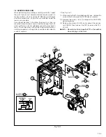
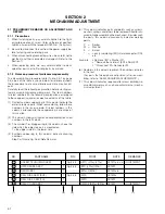
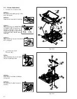
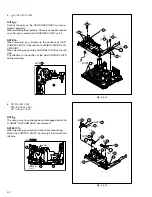
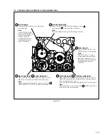
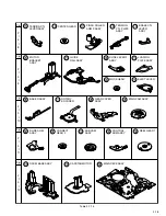
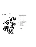
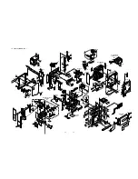
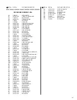
Fig. 2-4-10
9.
fl
BASE R ASSY
‡
ROTARY ENCODER
°
GEAR COVER ASSY
·
MAIN CAM ASSY
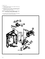
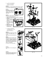
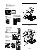
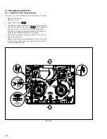
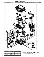
Fig. 2-4-11
10.
‚
SLIDE ARM ASSY
¡
CONNECT GEAR 2
™
SUB CAM ASSY
£
CONTROL ARM ASSY
¢
REEL GEAR 1
(S
a)
20
26
(S
b)
21
26
(S )
27
23
(S )
27
(L )
26
22
(S
b)
25
28
(S
b)
26
28
(S
a)
24
28
27
29
28
26
NOTE
26
NOTE
27
NOTE
29
32
33
31
30
34
(S )
32
27
NOTE
30
NOTE
31
NOTE
33
NOTE
32
NOTE
34
NOTE
fl
:
When mounting, fold the sliding
part to the inner side.
NOTE
·
:
When mounting, pay attention to
the correct positioning.
NOTE
‡
:
When mounting, pay attention to
the correct positioning and the
FPC layout.
NOTE
‚
:
When mounting, pay attention to the
correct positioning and the FPC lay-
out.
NOTES
™
/
£
/
¢
:
When mounting, pay attention to the correct positioning and
the FPC layout.
NOTE
¡
:
When mounting, pay attention to the posi-
tion of the front and back.
NOTE
26
NOTE
27
NOTE
29
NOTE
30
NOTE
(TOP)
(BOTTOM)
31
NOTE
/
32 33
32
33
NOTE
34

