3-1
SECTION 3
ELECTRICAL ADJUSTMENT
3
.1
PREPARATION
1. Precaution
Both the camera and deck sections of this model needs a
personal computer for adjustment except simple adjust-
ment with potentiometers. If some of the following parts is
replaced for repair or other reason, the repaired set must
be adjusted with a personal computer.
• OP block
• E
2
PROM (IC1003 of MAIN board)
• MONITOR
• E
2
P ROM (IC7603 of MONITOR board)
In the event of malfunction with electrical circuits, trouble-
shooting with the aid of proper test instruments most be
done first, and then commence necessary repair, replace-
ment and adjustment, etc.
1. In case of wiring to chip test points for measurement, use
IC clips, etc. to avoid any stress.
2. Since connectors are fragile, carefully handle them in
disconnecting and connecting.
3. Shortcircuit between operation un it and DECK chassis.
2. Required test equipment
1. Color TV monitor.
2. AC power adapter/charger
3. Oscilloscope (dual-trace type, observable 100 MHz or
higher frequency)
Note:
It is recommended to use one observable 300 MHz or
higher frequency.
4. Digital voltmeter
5. Frequency counter (with threshold level adjuster)
6. Personal computer
3. Required adjustment tools
For detsails of special jigs necessary for adjustment, refer to
page 1-2 and 1-3 of the Section 1.
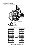
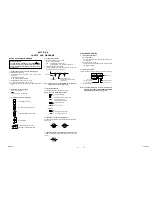
Fig. 3-2-1 Connection for Service support system
3
.2 SETUP
1. Setup for electrical adjustment with personal computer
Service Support
System software
RS232C
COM Port
PC CABLE
EXTENSION CONNECTOR
Personal Computer
MENU
JLIP
/ EDIT
J
10
1
20
CN1010
(JIG CONN.)
TL3501
REC MON
11
JIG CONNECTOR
CABLE
1
COVER
(JIG)
Note) For supplying the power
through the coupler by
removing the cover (for jig),
use this extension connector
double for connecting the
jig connector cable.
Summary of Contents for GR-DVM90U
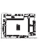
Page 45: ...5 4 3 2 1 A B C D E F G H 4 1 BOARD INTERCONNECTIONS 4 3 4 4 ...
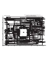
Page 75: ...5 4 3 2 1 A B C D E F G H 4 37 POWER SYSTEM BLOCK DIAGRAM 4 79 4 80 ...
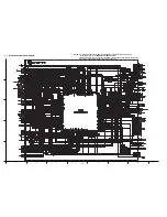
Page 76: ...5 4 3 2 1 A B C D E F G H 4 38 VIDEO SYSTEM BLOCK DIAGRAM 4 81 4 82 ...
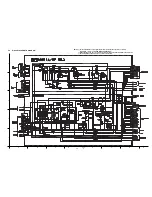
Page 77: ...5 4 3 2 1 A B C D E F G H 4 39 REGULATOR SYSTEM BLOCK DIAGRAM 4 83 4 84 ...


