


2-7
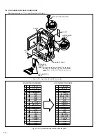
Fig. 2-2-12
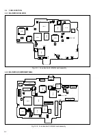
Fig. 2-2-13
2.2.5 Disassembly/assembly
1.
A
Cassette housing assembly
2
(S1)
3
(S1)
Cassette
housing
assembly
1
(S1)
Slide deck assembly
/Main deck assembly
(L1b)
(L1a)
(L1a)
(L1c)
Note 1c
(L1d)
(L1b)
A
Note 1b
2.
Reel disk (SUP) assembly
Reel disk (TU) assembly
Reel cover assembly
Note 1a:
Shift the mechanism mode
from the STOP mode to the
EJECT mode.
Note 1b:
Reassemble the cassette
housing assembly to the
mechanism as the cancel lever
is moved in the direction of the
arrow.
Note 1c:
When reassembling the cas-
sette housing to the mecha-
nism, make sure that there is
no deformation in the frame or
no damage to the switches,
etc.
Note 1d:
After reassembling the compo-
nent parts, check the mecha-
nism operation in the PLAY
mode.
For details of checking method,
refer to “2.2.8 assembling slide
deck assembly and main deck
assembly”.
<STOP mode>
<EJECT mode>
<PLAY mode>
Note 2a:
When removing the reel disk assembly, be careful not to break
the brake pad which applies lateral pressure to the reel disk.
Note 2b:
Be careful not to make a mistake in installing the reel disk.
The SUP reel disk and TU reel disk can be distinguished from
each other by the appearance as shown below.
Note 2c:
When removing the reel cover assembly, pay heed to the guide
arm assembly. For, the guide arm assembly is just inserted
into the slide deck assembly from the upside and it is apt to
come off after the reel cover assembly is removed.
Note 2d:
When fitting the reel cover assembly to the set, carefully tighten
the screw with the specified tightening torque of 0.069N·m
(0.7kgf·cm).
(SUP)
(TU)
2a
2b
2c
2c
(W2)
(W2)
(W2)
6
(S2b)
4
(S2a)
5
(S2a)
2a
2b
Slide deck assembly
/Main deck assembly
Note 2a
Note 2c
Note 2a
Note 2c
Note 2b
Note 2b
Summary of Contents for GR-DVM90U
Page 45: ...5 4 3 2 1 A B C D E F G H 4 1 BOARD INTERCONNECTIONS 4 3 4 4 ...
Page 75: ...5 4 3 2 1 A B C D E F G H 4 37 POWER SYSTEM BLOCK DIAGRAM 4 79 4 80 ...
Page 76: ...5 4 3 2 1 A B C D E F G H 4 38 VIDEO SYSTEM BLOCK DIAGRAM 4 81 4 82 ...
Page 77: ...5 4 3 2 1 A B C D E F G H 4 39 REGULATOR SYSTEM BLOCK DIAGRAM 4 83 4 84 ...


