

2-10
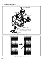
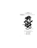
Fig. 2-2-18
7.
Loading brake assembly/ Guide pin (S)
Pad arm assembly/
Slide guide plate assembly
Collar/ Collar/ Sub brake assembly
Control plate assembly
Note 7a:
Don’t remove these parts unreasonably. If they are removed
for some reason, be very careful not to lose them.
Note 7b:
When reinstalling the sub brake assembly, set the control plate
assembly so that its hook is set in the
‹
part of the sub brake
assembly.
Note 7c:
Since the slide guide plate assembly controls the slide deck
assembly so that it exactly slides the main deck assembly, it
must exactly be assembled in the PLAY mode. Therefore,
temporarily fix the slide guide plate assembly in this stage.
For details of reassembling procedure, refer to “2.2.8
Assembling slide deck assembly and main deck as-
sembly” on page 2-15.
Note 7d:
The pad arm assembly controls the tension level of the ten-
sion arm assembly. For adjustment of the tension arm as-
sembly, refer to page 2-8.
Note 7e:
When reinstalling the load brake assembly, slightly lift the
slide deck assembly upwards because the lower part of the
load brake assembly sticks out of the slide deck assembly.
Fig. 2-2-19
8.
Tension lever assembly/ Slide lever assembly
Brake control lever assembly
Note 8a, 8b, 8c:
For refitting the respective parts, refer to the following figures
7a
(W7)
(W7)
(W7)
(W7)
(P7d)
Note 7e
Note 7c
Note
7a
Note 7b
Note 7d
(L7a)
(W7)
11
(S7b)
10
(S7a)
7b
7d
7g
7c
7e
(P7a)
(P7b)
(P7c)
(L7b)
(L7d)
(L7c)
7f
7h
8b
8a
8c
Note 8c
Note
8b
Note 8a
Note 7b
Tension lever assembly
Slide lever assembly
Brake control lever
assembly
7a
7c
7e
7h
7f
7d
7b
7g
8a
8c
8b
8a
8b
8c
Summary of Contents for GR-DVM90U
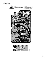
Page 45: ...5 4 3 2 1 A B C D E F G H 4 1 BOARD INTERCONNECTIONS 4 3 4 4 ...
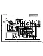
Page 75: ...5 4 3 2 1 A B C D E F G H 4 37 POWER SYSTEM BLOCK DIAGRAM 4 79 4 80 ...
Page 76: ...5 4 3 2 1 A B C D E F G H 4 38 VIDEO SYSTEM BLOCK DIAGRAM 4 81 4 82 ...
Page 77: ...5 4 3 2 1 A B C D E F G H 4 39 REGULATOR SYSTEM BLOCK DIAGRAM 4 83 4 84 ...