2-16
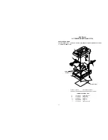
b
a
c
<PLAY mode>
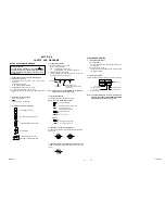
2.2.9 Locating tension pole
Fig. 2-2-26
Locating procedure
1. Enter the mechanism assembly into the PLAY mode.
(Refer to page 2-2.)
2. When the “
” part is positioned down, make sure that
the part “a” of the tension arm assembly is located within
the range of “b”.
3. If the part “a” is out of the range, turn the pin “c” to
adjust the position.
Summary of Contents for GR-DVM90U
Page 45: ...5 4 3 2 1 A B C D E F G H 4 1 BOARD INTERCONNECTIONS 4 3 4 4 ...
Page 75: ...5 4 3 2 1 A B C D E F G H 4 37 POWER SYSTEM BLOCK DIAGRAM 4 79 4 80 ...
Page 76: ...5 4 3 2 1 A B C D E F G H 4 38 VIDEO SYSTEM BLOCK DIAGRAM 4 81 4 82 ...
Page 77: ...5 4 3 2 1 A B C D E F G H 4 39 REGULATOR SYSTEM BLOCK DIAGRAM 4 83 4 84 ...


