2-12
11e
24
(S11)
22
(S11)
20
(S11)
Note 11
21
(S11)
19
(S11)
18
(S11)
(W11)
23
(S11)
11d
11c
11b
11a
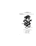
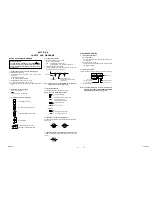
Fig. 2-2-22
11.
Catcher (T) assembly/ Capstan motor
Charge arm assembly/ Sub cam gear
PWB holder
Note 11:
The following figure shows how to put the charge arm assem-
bly and sub cam gear assembly together.
11d
11c
11a
11c
11e
11b
11d
Summary of Contents for GR-DVM90U
Page 45: ...5 4 3 2 1 A B C D E F G H 4 1 BOARD INTERCONNECTIONS 4 3 4 4 ...
Page 75: ...5 4 3 2 1 A B C D E F G H 4 37 POWER SYSTEM BLOCK DIAGRAM 4 79 4 80 ...
Page 76: ...5 4 3 2 1 A B C D E F G H 4 38 VIDEO SYSTEM BLOCK DIAGRAM 4 81 4 82 ...
Page 77: ...5 4 3 2 1 A B C D E F G H 4 39 REGULATOR SYSTEM BLOCK DIAGRAM 4 83 4 84 ...


