4.6.6 Fuse Replacement
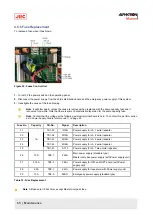
To replace a fuse when it has blown:
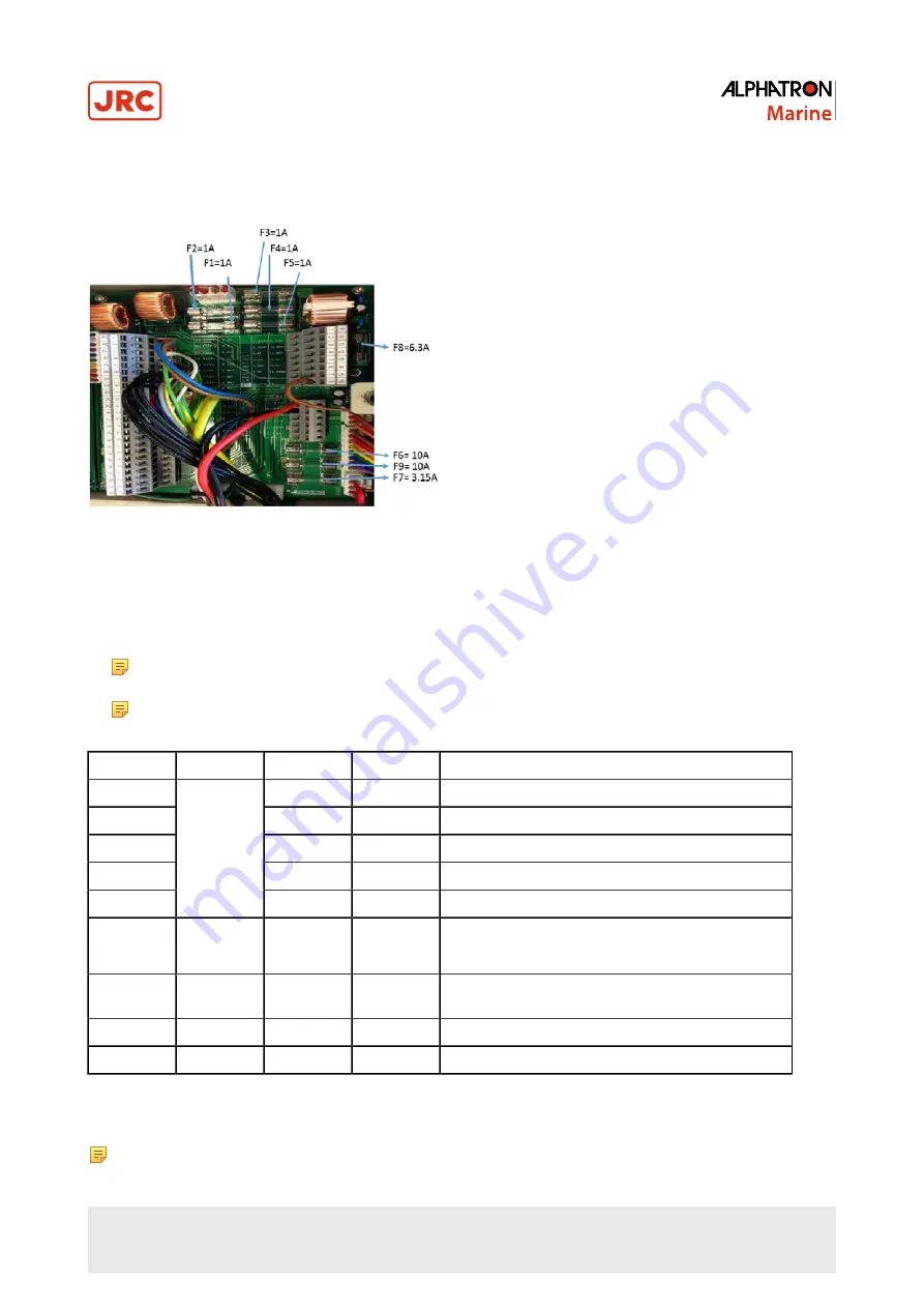
Figure 39: Fuses Control Unit
1. Turn OFF the power switch on the operating panel.
2. Disconnect the power supply from the ship’s distribution board and the emergency power supply of this system.
3. Investigate the cause of the fuse blowing.
Note It will blow again, unless the cause is removed when replaced with the same capacity fuse and it
recovered for a while. Note that there is some characteristic dispersion for the same capacity fuse.
Note Confirm that the voltage at the following external terminal board is zero. To confirm this, perform action
as in Power Supply Failure (alarm code 1) on page 60.
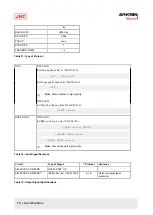
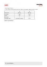
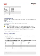
Fuse No.
Capacity
TB-No.
Signal
Description
F1
TB1-33
1R24+
Power supply for ch. 1 serial repeater
F2
TB1-38
2R24+
Power supply for ch. 2 serial repeater
F3
TB1-43
3R24+
Power supply for ch. 3 serial repeater
F4
TB1-48
4R24+
Power supply for ch. 4 serial repeater
F5
1A
TB1-21
ST15
Power supply for ch. 1 step motor repeater
F6
10A
TB3-1
24M+
Main power supply (standard type)
Master compass power supply (with Power supply unit)
F7
3.15A
TB3-3
24B+
Power supply for ICIF and IOPT board (with Power
supply unit)
F8
6.3A
TB2-1
24R+
Power supply for repeaters (with Power supply unit)
F9
10A
TB3-5
24BT+
Emergency power supply (standard type)
Table 19: Fuse Replacement
Note All fuses are
∅5.2x20mm,
except Master Compass fuse.
65 | Maintenance
Summary of Contents for Alpatron AlphaMidiCourse
Page 1: ...AlphaMidiCourse Gyro Compass Installation and Operation Manual www jrc am ...
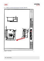
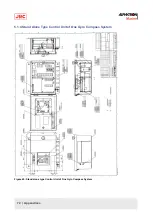
Page 68: ...5 1 1 Outline Control Unit One Gyro Compass System Figure 41 Control Box 68 Appendices ...
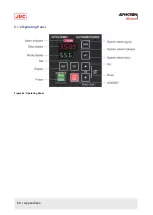
Page 69: ...5 1 2 Operating Panel Figure 42 Operating Panel 69 Appendices ...
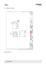
Page 70: ...5 1 3 Master Compass Figure 43 Main Unit 70 Appendices ...
Page 71: ...Figure 44 Open Gyro Compass 71 Appendices ...
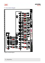
Page 73: ...5 1 5 Connection Diagram Figure 46 Connection Diagram 73 Appendices ...
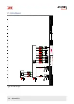
Page 74: ...5 1 6 Cable Diagram Figure 47 Cable Diagram 74 Appendices ...
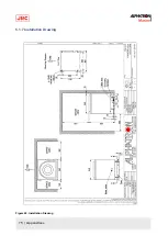
Page 75: ...5 1 7 Installation Drawing Figure 48 Installation Drawing 75 Appendices ...
Page 76: ...5 1 8 Terminal Board Figure 49 Terminal Board 76 Appendices ...

