1.7 DIP Switch Settings
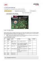
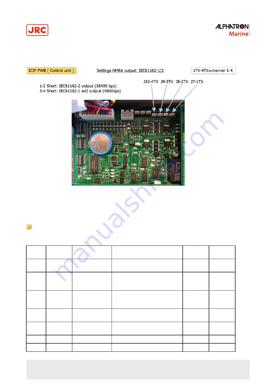
The AlphaMidiCourse Gyro Systems include several Dip Switch Settings.
Figure 17: DIP Switch Settings
With the exception of the two switches on the ICIF board in the Control Unit, no switches require to be set when installing
the system. These two switches have been set to configure the Control Unit to match the type of gyro system (Alphatron
Midi and Alphatron Midi HS) and to activate an external heading sensor.
Note These Dip Switch Settings are read when the system is started up. Any changes made while the system is
running will therefore not take effect before the system is restarted.
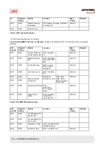
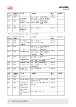
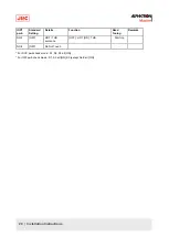
Dip Switch Setting Master Compass
S1
Standard
Setting
Details
Function
Read
Timing
Remarks
NO.1
[OFF]
Master Compass
type
[OFF] : Standard [ON] : HSC
Start Up
NO.2
[OFF]
Display of Master
Compass Type
[ON] : In standard case displayed
as "Std". In HSC case displayed as
"HIGH". (LED on mcc PWB)
All Time
NO.3
[OFF]
Rate Limiter
[ON] : Rotation of Master Compass
is stopped at turning rate of more
than
30˚/
sec.
All Time
NO.4
[OFF]
Start Up Sequence
Standard [ON] : Leveling time is 2
minutes
Start Up
HSC [ON] : Special sequence for
dumping test
NO.5
[OFF]
Do Not Touch
*
NO.6
[OFF]
Do Not Touch
*
25 | Installation Instructions
Summary of Contents for Alpatron AlphaMidiCourse
Page 1: ...AlphaMidiCourse Gyro Compass Installation and Operation Manual www jrc am ...
Page 68: ...5 1 1 Outline Control Unit One Gyro Compass System Figure 41 Control Box 68 Appendices ...
Page 69: ...5 1 2 Operating Panel Figure 42 Operating Panel 69 Appendices ...
Page 70: ...5 1 3 Master Compass Figure 43 Main Unit 70 Appendices ...
Page 71: ...Figure 44 Open Gyro Compass 71 Appendices ...
Page 73: ...5 1 5 Connection Diagram Figure 46 Connection Diagram 73 Appendices ...
Page 74: ...5 1 6 Cable Diagram Figure 47 Cable Diagram 74 Appendices ...
Page 75: ...5 1 7 Installation Drawing Figure 48 Installation Drawing 75 Appendices ...
Page 76: ...5 1 8 Terminal Board Figure 49 Terminal Board 76 Appendices ...

