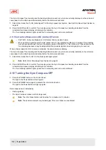
Note The trouble shooting and repair should be carried out by the engineer according to the results of the
checks of the faulty items.
4.2 Periodical Checks
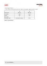
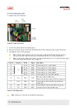
Use the periodical check table for the periodical check. See Periodic Check Table 1 on page 78
Frequency of the checks are:
1. Items to be executed once a day.
2. Once a half year / once a year.
Checked items are regarded as normal, or not, by comparing their condition as at installation time on the ship as a
standard.
1. Copy and use periodical check table (including operational check) [once a day], in the Appendix. See Figure 51:
Periodic Check Table 1 on page 78
Note When table is full file it.
2. Copy and use periodical check table (including operational check) [once a half year / once a year], in the Appendix.
See Figure 52: Periodic Check Table 2 on page 79
Note When table is full file it.
4.3 Warning Label Check
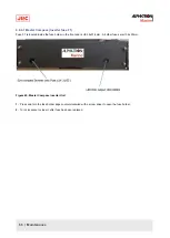
Always check and clean warning labels so they are easy to read.
When warning labels become dirty or detached, request new ones from Alphatron Marine.
4.4 Spare Parts
Part Name
Part No.
Weight 9.0 G
10210101-
Weight 3.0 G
10210102-
Weight 3.8 G
10210103-
Weight 2.3 G
10210104-
Weight 1.2 G
10210105-
Weight 0.95 G
10210106-
Weight 0.6 G
10210107-
Weight 0.3 G
10210108-
Weight 0.17 G
10210109-
Weight 6.6 G
10210110-
Guide Screw [A]
11002595-
Guide Screw [A]
11002596-
Sensitive Element
3107.9152
Brush
3107.9154
Step Motor
3107.9158
58 | Maintenance
Summary of Contents for Alpatron AlphaMidiCourse
Page 1: ...AlphaMidiCourse Gyro Compass Installation and Operation Manual www jrc am ...
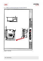
Page 68: ...5 1 1 Outline Control Unit One Gyro Compass System Figure 41 Control Box 68 Appendices ...
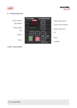
Page 69: ...5 1 2 Operating Panel Figure 42 Operating Panel 69 Appendices ...
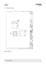
Page 70: ...5 1 3 Master Compass Figure 43 Main Unit 70 Appendices ...
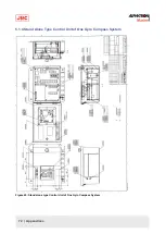
Page 71: ...Figure 44 Open Gyro Compass 71 Appendices ...
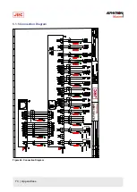
Page 73: ...5 1 5 Connection Diagram Figure 46 Connection Diagram 73 Appendices ...
Page 74: ...5 1 6 Cable Diagram Figure 47 Cable Diagram 74 Appendices ...
Page 75: ...5 1 7 Installation Drawing Figure 48 Installation Drawing 75 Appendices ...
Page 76: ...5 1 8 Terminal Board Figure 49 Terminal Board 76 Appendices ...

