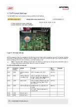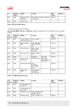
ICIF
pwb S2
Standard
Setting
Details
Function
Read
Timing
Remarks
NO.5
[OFF]
NO5.[OFF] NO6.
[OFF] ; 1sec
NO5.[ON] NO6.
[OFF] ; 200msec
NO.6
[OFF]
Serial Signal
Transmit
Frequency
IEC61162-1 ed.2
NO5.[OFF] NO6.
[ON] ; 100msec
NO5.[ON] NO6.
[ON] ; Invalid
(1sec)
Start Up
NO.7
[OFF]
Do Not Touch
-
NO.8
[OFF]
System Select
Information
Contact
[OFF] : no [ON] : yes
Start Up
¹ Standard set to off, for pendulum ferry use external interface!
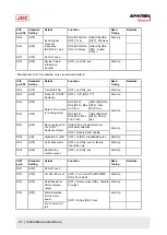
ICIF
pwb S3
Standard
Setting
Details
Function
Read
Timing
Remarks
NO.1
[OFF]
Timer Start Up
[OFF] : no [ON] : yes
Start Up
NO.2
[OFF]
Talker ID of "ROT"
Sentence
[OFF] : "HE" [ON] : "TI"
Start Up
NO.3
[OFF]
NO3.[OFF],
NO4.[OFF] : Max
30.0˚/
min.
[NO3.[ON] NO4.
[OFF] : Max
300.0˚/
min
NO.4
[OFF]
Rate of Turn Scale
for Analog meter
NO3.[OFF],
NO4.[ON] : Max
300.0˚/
min.
[NO3.[ON] NO4.
[OFF] : Do Not
Set
Start Up
Valid at time of external sensor
(standard) selection
NO.5
[OFF]
Ban or permission
of an "RoT"
Sentence Output
[OFF] : disable [ON] : enable
Start Up
NO.6
[ON]
Alphatron or other
[OFF] :no [ON] : AlphaMidiCourse
Start Up
NO.7
[OFF]
Unit check mode
[OFF] : no [ON] : yes for factory
inspection only
Start Up
NO.8
[OFF]
Buzzer stop
contact output
[OFF] : no [ON] : yes
Start Up
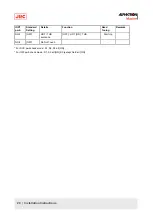
IOPT
pwb
Standard
Setting
Details
Function
Read
Tuning
Remarks
NO.1
[OFF]
Do Not Touch
-
NO.2
[OFF]
For AGI-80 or not
[OFF] : For normal TG-8000/8500
[ON] : For AGI-80
Start Up
NO.3
[OFF]
Able/Disable for
HDG sentence
output
[OFF] : Able to output [ON] : Disable
to output
Start Up
Alarm detection
time for main
power
Start Up
NO.4
[OFF]
Fail / Power Unit
fail
[OFF] : 300ms [ON] : 2sec
27 | Installation Instructions
Summary of Contents for Alpatron AlphaMidiCourse
Page 1: ...AlphaMidiCourse Gyro Compass Installation and Operation Manual www jrc am ...
Page 68: ...5 1 1 Outline Control Unit One Gyro Compass System Figure 41 Control Box 68 Appendices ...
Page 69: ...5 1 2 Operating Panel Figure 42 Operating Panel 69 Appendices ...
Page 70: ...5 1 3 Master Compass Figure 43 Main Unit 70 Appendices ...
Page 71: ...Figure 44 Open Gyro Compass 71 Appendices ...
Page 73: ...5 1 5 Connection Diagram Figure 46 Connection Diagram 73 Appendices ...
Page 74: ...5 1 6 Cable Diagram Figure 47 Cable Diagram 74 Appendices ...
Page 75: ...5 1 7 Installation Drawing Figure 48 Installation Drawing 75 Appendices ...
Page 76: ...5 1 8 Terminal Board Figure 49 Terminal Board 76 Appendices ...

