2
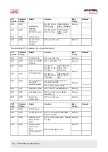
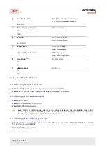
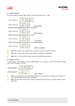
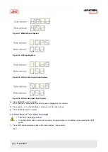
True Bearing 2: ***
***.*
ESt or GYt
ESt = External Sensor true bearing
GYt = Gyro-compass true bearing
3
Master Compass Bearing:
***.*
C.P.S
C.P.S. = Compass
4
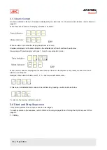
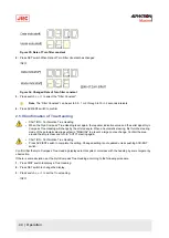
Latitude: ***.*
***.*
LA.n or LA.S
LA.n = Latitude North
LA.S = Latitude South
5
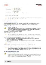
Ship's speed: ***.*
***.*
G.Sd or H.Sd or L.Sd or S.Sd
G.Sd = Gps.Speed
H.Sd = Hand.Speed
L.Sd = Log.Speed
S.Sd = Serial.Log.Speed
6
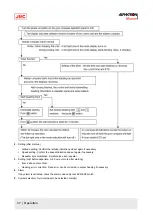
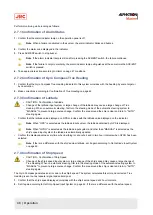
Rate of turn: ***.*
rt. = Rate of turn
****
rt.
7
Alarm content:
****
Err
Err = Error
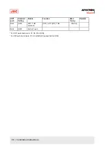
Table 7: Data / Mode Menu Structure
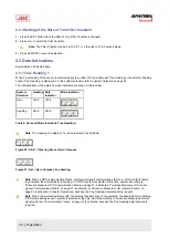
2.2.1 Steering Sensor Selection
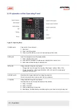
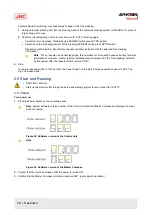
1. Press the GYRO button to select the Gyro Compass and press ACK/ENT.
2. Press the EXT button to select the External Heading Sensor and press ACK/ENT.
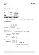
2.2.2 Setting of the Latitude Input
1. Press the SET button.
2. Press
▼or▲
to select either GPS or GYro.
3. Press ACK/ENT to enter selection.
Note When H.Sd (MANUAL) was selected, as the latitude is displayed in the Data Indicator, press
▼or▲
to
set the latitude and press ACK/ENT again. The herein after calculated latitude by the ship's speed and the
True bearing is indicated by using the manually entered latitude.
2.2.3 Setting of the Ship's Speed Input
1. Press the SET button and use
▼or▲
to select one of the following modes: G.Sd (GPS), H.Sd (MANUAL), l.sD (LOG
PULSE), or S.Sd (LOG SERIAL).
2. Press ACK/ENT to enter selection.
32 | Operation
Summary of Contents for Alpatron AlphaMidiCourse
Page 1: ...AlphaMidiCourse Gyro Compass Installation and Operation Manual www jrc am ...
Page 68: ...5 1 1 Outline Control Unit One Gyro Compass System Figure 41 Control Box 68 Appendices ...
Page 69: ...5 1 2 Operating Panel Figure 42 Operating Panel 69 Appendices ...
Page 70: ...5 1 3 Master Compass Figure 43 Main Unit 70 Appendices ...
Page 71: ...Figure 44 Open Gyro Compass 71 Appendices ...
Page 73: ...5 1 5 Connection Diagram Figure 46 Connection Diagram 73 Appendices ...
Page 74: ...5 1 6 Cable Diagram Figure 47 Cable Diagram 74 Appendices ...
Page 75: ...5 1 7 Installation Drawing Figure 48 Installation Drawing 75 Appendices ...
Page 76: ...5 1 8 Terminal Board Figure 49 Terminal Board 76 Appendices ...

