1 Installation Instructions
This chapter explains the configuration, specifications and structure of this system.
1.1 Installation Guidelines
Master Compass
1. Select a mounting location where the deck is horizontal, flat, has little vibration and pitch/roll is as small as possible.
Note Mounting location should have sufficient space for installation and servicing. Refer dimensional
drawing Figure 48: Installation Drawing on page 75.
2. Position the compass on or parallel to the vessel's horizontal center line, with the bow indication on the top of the
case pointing towards the vessel's bow.
3. Use the datum line in the front and back of the compass to line up the unit.
Note be sure to install all equipment cables more than 5m away from radio equipment feeders.
4.
Connect terminals marked
with the ground terminals of the vessel.
Note Shielded end of shielded cable to be finished close to the terminal board and connect to the ground
terminals of the vessel.
5. Do NOT use a megger for any tests!
Drawing on page 75.
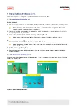
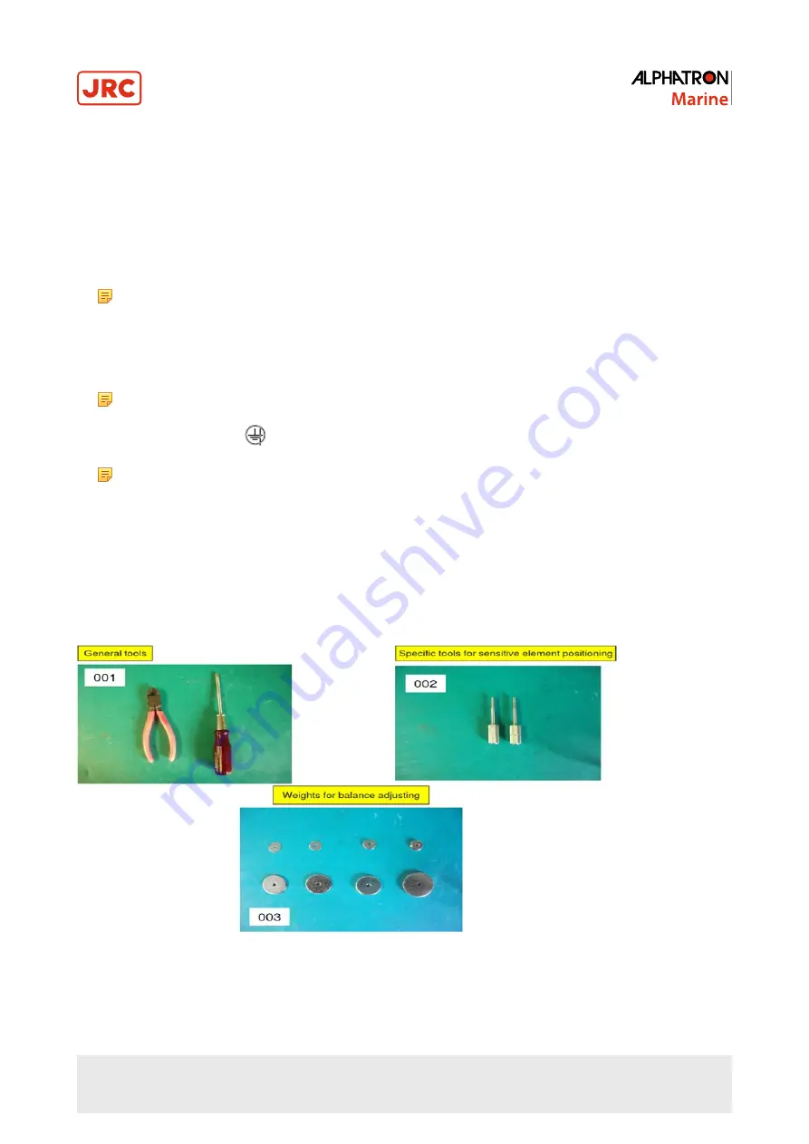
1.1.1 General and Specific Tools
General and Specific tools are required for installing the Gyro Sphere into the Master Compass, as shown in pictures
labeled 001, 002 and 003.
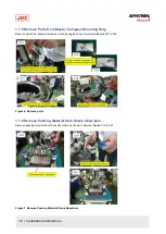
Figure 1: Special and Specific Tools
15 | Installation Instructions
Summary of Contents for Alpatron AlphaMidiCourse
Page 1: ...AlphaMidiCourse Gyro Compass Installation and Operation Manual www jrc am ...
Page 68: ...5 1 1 Outline Control Unit One Gyro Compass System Figure 41 Control Box 68 Appendices ...
Page 69: ...5 1 2 Operating Panel Figure 42 Operating Panel 69 Appendices ...
Page 70: ...5 1 3 Master Compass Figure 43 Main Unit 70 Appendices ...
Page 71: ...Figure 44 Open Gyro Compass 71 Appendices ...
Page 73: ...5 1 5 Connection Diagram Figure 46 Connection Diagram 73 Appendices ...
Page 74: ...5 1 6 Cable Diagram Figure 47 Cable Diagram 74 Appendices ...
Page 75: ...5 1 7 Installation Drawing Figure 48 Installation Drawing 75 Appendices ...
Page 76: ...5 1 8 Terminal Board Figure 49 Terminal Board 76 Appendices ...


