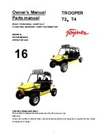
background image

Owner’s Manual


Parts manual 


READ THIS MANUAL CAREFULLY 
IT CONTAINS IMPORTANT SAFETY INFORMATION.


MINIMUM 
RECOMMENDED 
OPERATOR AGE:


FOR OFF-ROAD USE ONLY 

This vehicle is designed and manufactured for off-road use only. 

USA only; 

It does not confirm to federal motor vehicle safety standards, and operation on public streets, roads, 

or highways is illegal. 


16 

TROOPER 

T2

T4 

Summary of Contents for TROOPER T2

Page 1: ...TY INFORMATION MINIMUM RECOMMENDED OPERATOR AGE FOR OFF ROAD USE ONLY This vehicle is designed and manufactured for off road use only USA only It does not confirm to federal motor vehicle safety stand...

Page 2: ...e features and operation of this vehicle It also includes basic maintenance and inspection procedures If you have any questions regarding the operation or maintenance of your vehicle please consult a...

Page 3: ...rive 25 Pre drive Inspection 25 Operation instruction 27 Main switch 27 Battery switch 27 Gauges 28 Switches 28 Steering wheel 30 Pedal 31 Parking brake lever 31 Drive select lever 32 Differential con...

Page 4: ...54 Repair manual 55 Chassis wiring diagram 55 Engine wiring diagram 56 Chassis disassembly installation and repairment 56 Front suspension 56 Rear suspension 56 Driven system 56 Coolant system 56 Fuel...

Page 5: ...1 155 14 OTHER ACCESSORY 2 156 5T07D1 TRANSMISSION 157 1 CASE ACCESSORY 157 1 CASE ACCESSORY 158 2 COUNTERSHAFT 159 2 COUNTERSHAFT 160 3 INPUT SHAFT ASSY 161 3 INPUT SHAFT ASSY 162 3 INPUT SHAFT ASSY...

Page 6: ...6 Warranty policy...

Page 7: ...7...

Page 8: ...8...

Page 9: ...9...

Page 10: ...10 Parts order form warranty claim form...

Page 11: ...11 Service record form...

Page 12: ...12 Preventative maintenance and service log...

Page 13: ...13...

Page 14: ...14...

Page 15: ...15...

Page 16: ...16...

Page 17: ...stand all of the labels on your vehicle They contain important information for safe and proper operation of your vehicle Never remove any labels from your vehicle If a label becomes difficult to read...

Page 18: ...18...

Page 19: ...19...

Page 20: ...20...

Page 21: ...n and maintenance procedures and schedules described in this manual 11 Always keep both hands arms feet and legs inside the vehicle at all times during operation Keep your feet on the floorboard Never...

Page 22: ...han the floorboards on this model Remember that wet brakes may have reduced stopping ability Test your brakes after leaving water If necessary apply the brakes lightly while the vehicle is moving so t...

Page 23: ...oots gloves long pants and long sleeved shirt or jacket whenever you drive Although complete protection is not possible wearing proper gear can reduce the chance of injury when you drive The following...

Page 24: ...ER without proper instruction could increase your risk of an accident which could lead to serious injury or death Attempt supporting with your hands to the ground when the Off Highway Recreational veh...

Page 25: ...or even a flat tire can be a major inconvenience If your TROOPER has overturned or has been involved in a collision do not drive it until your TROOPER has been inspected by your dealer There may be da...

Page 26: ...Press the throttle to make sure it moves smoothly without sticking and snaps back automatically when it is released Clutch cable Check the free play of clutch cable and adjust if needed Press the clut...

Page 27: ...elease the key when the engine starts Do not operate the electric starter continuously for more than 5 seconds or starter damage could occur Wait at least 5 seconds between each operation of the elect...

Page 28: ...how much fuel you have in the fuel tank 2 a tachometer which shows the engine rotate speed 3 a speedometer This shows the riding speed in Km MPH 4 a coolant thermometer which shows the coolant tempera...

Page 29: ...ions z 2WD Power is routed to the back wheels only z 4WD Power is delivered to both the front and the back wheels z Front free the vehicle working with front differential z Front lock the vehicle work...

Page 30: ...if the temperature is above 1020 C 2150 F stop engine immediately Check coolant lever and add if low see authorized JOYNER dealer if temperature indicator stay on and overflow tank is full of coolant...

Page 31: ...he rest position fully when released z If anyone of them can t work well please correct the problem before operating the engine If you can t find or solve the problem yourself please get the help from...

Page 32: ...work and locked 2 handles control front differential and rear differential respectively Choose the work mode that you need according to the terrain situation The following work mode is available z 2DW...

Page 33: ...ment lever is back on its full lock position and the seat is locked in place 1 Pull seat lock lever under left leg upward 2 Move the Seats backwards or forwards As your need 3 Release the lock lever s...

Page 34: ...the latch plates as you pull the belts across above right shoulder left shoulder right leg left leg and among two legs Make sure the belt is not twisted and is not caught on any portion of the vehicl...

Page 35: ...sult in a strong possibility of severe personal injury or loss of life Before attempting to adjust the seat ensure that TROOPER is stopped Safari bed Safari bed can be lift up 1 Pull up the release le...

Page 36: ...ly is working smoothly and returns to idle when released Do not operate if pedal or engine throttle linkage fail to return to idle If unable to correct the problem through lubrication adjustment or re...

Page 37: ...w schedule The speed of vehicle The first 1000 km Max speed in each gear 1st Gear 12 4 MPH 2nd Gear 24 8 MPH 3rd Gear 37 2 MPH 4th Gear 52 7 MPH 5th Gear 65 1MPH Starting and operating instructions Be...

Page 38: ...brication system Liquid cooled 4stroke Upstanding double cylinder 1080cc 72mm 66 5mm 2 83 inch x2 62 inch 9 5 1 Electric starter Wet sumb Engine oil Type Recommended engine ail classification Quantity...

Page 39: ...Front shock absorber Rear shock absorber Coil spring oil damper Coil spring oil damper Wheel travel Front wheel travel Rear wheel travel 120mm 150mm Electrical Ignition system Generator system Batter...

Page 40: ...40 Indicator lights Reverse indicator light Coolant temperature warning light Charge indicator light Four wheel drive indicator light LED LED LED LED...

Page 41: ...he air filter if dusty blow off dust with clear and dry air If necessary replace with a new one Engine Lubrication 1 Engine oil replacement You must change the oil in the crankcase refer to Preventati...

Page 42: ...d recharge If the color of engine oil changes you need to replace the engine oil as above Check the engine oil level charge if the oil level is lower than L Transmission lubrication Oil replacement Yo...

Page 43: ...ential oil outlet plug Loosen the oil outlet plug in the differential Let the oil out fully c Remove the iron dust plug this plug has a magnet on it Iron dust caused by moving parts will stick to the...

Page 44: ...oolant tank volume j Close the reserve coolant case cap turn it clockwise and tighten it z Opening the radiator cap while the engine is hot can be hazardous Opening the radiator cap can spray the high...

Page 45: ...value is 900 RPM b Adjust the screw and adjust the idle speed to an ideal value c Repeat step b until the RPM of engine stables Spark plug inspection z Clean spark plug Check spark plug refer to Preve...

Page 46: ...ner torque 25N m 6 Connect high voltage wire in order Engine damage or working unsteadily may occur if 1 Not install the spark plug correctly 2 Use a forbidden spark plug To avoid damage follow the fo...

Page 47: ...ecessary to replace the belt When checking the wedge belt never start engine or body injury even death may occur Shift cable adjustment After a long time use more and more free play of shift cable mak...

Page 48: ...r decrease so adjust the shift cable refer to Preventative maintenance and service log 1 Loosen the adjustment nuts move the cable forwards or backwards according the situation repeat it until find a...

Page 49: ...lay of parking brake cable make parking brake power decrease so adjust the shift cable refer to Preventative maintenance and service log Throttle cable adjustment Differential lock cable adjustment Pa...

Page 50: ...s to change gearshift from 1 to 5 and reverse smoothly The shift lever should be vertical when the gear is in neutral If not adjust the shift cable and then tighten the nuts of the shift cable Front W...

Page 51: ...embly carefully 2 Remove four bolts on the transmission case lay down these carefully Caution When fix the four bolts in the transmission case you must tighten them according to the prescribed torque...

Page 52: ...spine shaft into the hole of the Clutch assy remove the six bolts on the Clutch pressure plate now It s clear Caution When fix the six bolts in the Clutch pressure plate You must tighten them accordin...

Page 53: ...nto the hole of the Clutch assy fix the six bolts on the Clutch pressure plate tighten them according to the prescribed torque 28 N M 6 Fix parts according to reverse operation to the disassembly S11...

Page 54: ...dimension A should be 0 98 inches greater than dimension B c To adjust the alignments loose the lock nuts on both sides of Front Tie Rods To make Dimension B smaller turn the rod to the left Turn the...

Page 55: ...55 Repair manual Chassis wiring diagram...

Page 56: ...56 Engine wiring diagram Chassis disassembly installation and repairment Front suspension Rear suspension Driven system Coolant system Fuel system Steering box Shift Brake Parking brake clutch...

Page 57: ...llation and repair Timing Belt 1 Configuration diagram 1 Water pump pulley 2 Timing belt cover upper 3 Timing belt cover Lower 4 Torsion shock absorber 5 Timing pulley damper 6 Tensioner 7 Crankshaft...

Page 58: ...2 Removing timing belt cover Torque 6 1N m 2 3 Remove tensional vibration damper 2 3 1 Fix the flywheel and prevent the gear ring from rotating 2 3 2 Remove bolt of tensional vibration damper 2 3 3 En...

Page 59: ...on of timing mark assemble according to original state 2 5 3 Make sure that the crankshaft timing pulley wheel mark is aligned with the mark of the oil pump 2 5 4 Remove the tensioner bolt and take of...

Page 60: ...s 2 8 5 1 If the water in the water pump is leaked which makes it necessary to refill the water continuously 2 8 5 2 There are much oil stains on the belt the belt should be replaced for the rubber wi...

Page 61: ...e front end of the air exhaust camshaft so as to make the positioning groove on the gear be aligned with the positioning pin on the end surface of the camshaft Then use screws to fix the clockwise gea...

Page 62: ...ns the key is to adjust the above mentioned stretcher fastening bolt by widening he spacing tighten the S A fixing bolt of the stretcher with the specified torque of 25 3N m 3 4 Install the baffle of...

Page 63: ...amper 3 6 Install timing belt cover Install seal strip in the position shown as right figure Install the position 1 and position 2 before cylinder head assembly install position 3 before tighten water...

Page 64: ...ver gasket 3 Camshaft timing pulley 4 Camshaft cover 5 Circular plug 6 Camshaft bearing cap 7 Exhaust camshaft 8 Intake camshaft 9 Oil seal 10 Spring retainer 11 Wave washer 12 Intake camshaft sub gea...

Page 65: ...et with a special tool Attention Manufacture a special tool according the right figure The special is necessary to prevent the camshaft to rotate 2 3 Removal of camshaft bearing cover 2 3 1 Align the...

Page 66: ...camshaft slave gear 2 6 1 Use the special tool as shown in the right figure Clip the camshaft tightly and turn the gear to keep the bite state of master and slave gear remove the fixing bolts of slave...

Page 67: ...2 7 3 Checks on camshaft meshing clearance 1 Put camshaft into cylinder head 2 Make sure the front mark on bearing cover and shaft number is ok and then tighten bolt 3 Fix air inlet camshaft and then...

Page 68: ...l clearance of the camshaft 3 3 1 Smear lubricating oil at the camshaft gear section and the cylinder cover axial diameter section 3 3 2 Fix the camshaft slave gear by roughly adjusting on the cylinde...

Page 69: ...er head end surface after pressing 1 1mm 3 7 Smear engine oil on the oil seal installation port of cylinder head camshaft oil seal edge of blade and outside ring use M10 bolt length 50 60 mm and SST p...

Page 70: ...over the cylinder head with cylinder head cover tighten the bolts according the right figure Torque 6 1N m 4 Routine check 4 1 Standard of valve clearance 4 2 Align the timing marks on the drive gear...

Page 71: ...valve lifter towards inside 4 4 2 Rotate camshaft and the cam press valve lifter down 4 4 3 Load the special tool at the top of the valve lifter around the valve lifter and then rotate camshaft to mak...

Page 72: ...e the selected adjusting gasket to adjust the throttle clearance Attention Install the feeler with the identification mark facing downwards 4 4 3 5 Rotate camshaft to make cam top downwards and the th...

Page 73: ...0 1Nm 2 Cylinder head 3 Weather seal I 4 Cylinder head gasket 5 Adjust shim 6 Valve lifter 7 Keeper 8 Valve spring seat 9 Valve spring 10 Intake valve 11 Exhaust valve 12 Valve oil seal 13 Valve seat...

Page 74: ...alve 2 6 Removal of valve oil seal and valve spring washer 2 7 Clearing 1 The accumulated carbon residue covered on the valve must be cleared 1 Use scraper to clear the cylinder cover the air inlet an...

Page 75: ...aliper to measure the outer diameter 3 3 2 2 Work out the differences of the measured values If it is above the specified limits the throttle or the guiding pipe must be replaced Attention The measure...

Page 76: ...the proper position No excessive driving should be exerted Pay attention to the specifications in the operation Driving in depth of throttle guiding pipe 3 3 3 4 Use reamer to grind the inner diameter...

Page 77: ...the cylinder head with special use auxiliary tools smear fluid sealant before pressing pressing height is shown as the illustration Attention Pay attention that the vertical degree of its pressing de...

Page 78: ...s use special tools to install the locking blocks for the throttle spring stands 3 4 3 4 Installation of the throttle thrusting rod and throttle spacing by adjusting the separation cushions 3 4 3 5 In...

Page 79: ...to leak oil Water pump 1 Configuration diagram the dismounting and assembling of the cylinder body should be done in the following procedures 1 O ring non reusable2 Oil pump body3 Weather seal 2 Dismo...

Page 80: ...if the turning is OK and if it is smoothly lubricated 5 Installation 5 1 Install the dustproof sealing stripes 5 2 Install the water pump principal body Tighten with a torque of 25 1 5N m 5 3 Install...

Page 81: ...r oil seal bracket 2 Dismounting 2 1 The engine being turned upside down on the dismounting frame take off the bolts Remove the oil pan from the cylinder body Attention Do not make the oil pan flange...

Page 82: ...For the mating surfaces of the oil bottom case oil pump and oil seal stands For the mating surfaces of the rear oil seal stand and oil pump scraper and chipping chisel or some other tools may be used...

Page 83: ...ttention The weather seal are not reusable 4 2 2 Remove the oil pump cover Attention The bolt is assembled with glue loosen it with screw driver according to the illustrations 4 2 3 Remove the driven...

Page 84: ...ng 4 3 1 1 Follow the mark on the interior and exterior gears of the oil pump to place it into the lubricating oil pump body on the cylinder body 4 3 1 2 Use a feeler to measure the clearance between...

Page 85: ...xposed part of the outer edge of the oil seal after being pressed in should be less than 0 5mm 4 4 2 Assembling of the oil pump pressure relief valve and split pins Attention The split pins are not re...

Page 86: ...diagram 5 2 Disintegration 5 2 1 Use a flat screwdriver to remove the rear oil seal Attention The oil seals are not reusable 5 3 Checks Check to see if the tears and wears of the lip section of the o...

Page 87: ...sealing stands shown as the right figure Grease Letai 5699 Attention The liquid sealing silica is to be smeared to the mating section of the oil seal stands and cylinder body surface with a width of 3...

Page 88: ...a line diameter of 3 4mm without any broken section Make the assembly in 15 minutes after the application of silica 6 4 3 Tighten in the sequence shown in the right figure with the torque of 6 1N m fr...

Page 89: ...haft bush 7 Thrust washer 8 Cylinder block 9 No 1 compression ring 10 No 2 compression ring 11 Oil ring 12 Piston 13 Connecting rod 14 Piston pin 2 Disintegration of crankshaft connecting rod mechanis...

Page 90: ...s cylinders should be placed in good order 2 2 2 Clean the bush and axle diameter 2 2 3 Place clearance gauge on the connecting bearing diameter Tighten bush cover according to regulated torque torque...

Page 91: ...hammer Attention Put the parts and components of various cylinders in good order 2 3 Use a caliper to measure the crankshaft axial clearance If the axial clearance is above the limits it is needed to...

Page 92: ...ring cover and measure the maximum width of the spacing If it goes beyond the limit replace the bush Benchmark 0 025 0 069mm Limit 0 10mm 2 4 5 Remove Main bearing cover Crankshaft Crankshaft bush Thr...

Page 93: ...us parts with detergents Attention Do not use metal brush or some other hard substance to do the cleaning 4 Routine checks 4 1 Cylinder block 4 1 1 Checks on the levelness of cylinder top surface 1 Us...

Page 94: ...rk out the clearance on the basis of the size difference between the hole diameter and the pin diameter Replace the piston pin or the piston if the result exceeds the benchmark value Benchmark 0 004 0...

Page 95: ...ody or bore the cylinder if the measured results exceed the limits Benchmark 0 018 0 03 Limit 0 10 Reference The clearance between the piston and the cylinder hole is subject to the innermost diameter...

Page 96: ...iston connecting rod and piston pin in the following specified procedures 5 1 1 1 Smear lubricating oil to the connecting rod pin hole and make the assembly according to the marks for the same unit an...

Page 97: ...this side upper side of the crankshaft before installing it 5 3 3 The side thrust chip with oil sink should face outward crankshaft handle for installation on the cylinder body bearing stand Attentio...

Page 98: ...piston the connecting rod and the surfaces of the other related moving parts 5 4 4 Make sure the frontward indication mark on the piston Should be frontward and assemble the piston connecting rod Ay w...

Page 99: ...99 Electric injection system...

Page 100: ...100...

Page 101: ...101...

Page 102: ...102...

Page 103: ...103...

Page 104: ...104...

Page 105: ...105...

Page 106: ...106...

Page 107: ...107...

Page 108: ...108...

Page 109: ...109...

Page 110: ...110...

Page 111: ...111...

Page 112: ...112...

Page 113: ...113...

Page 114: ...114...

Page 115: ...115...

Page 116: ...116...

Page 117: ...117...

Page 118: ...118...

Page 119: ...119...

Page 120: ...120...

Page 121: ...121...

Page 122: ...122...

Page 123: ...123...

Page 124: ...124...

Page 125: ...125...

Page 126: ...126...

Page 127: ...127...

Page 128: ...128...

Page 129: ...129...

Page 130: ...130...

Page 131: ...131...

Page 132: ...132...

Page 133: ...133...

Page 134: ...134...

Page 135: ...135...

Page 136: ...136...

Page 137: ...137...

Page 138: ...138...

Page 139: ...RING 1 8 372 1307041 WATER PUMP WASHER 1 9 372 1307018 SEAL STRIP 2 1 10 Q1840825 BOLT 11 11 372 1307019 SEAL STRIP 3 1 12 372 1307012 SEAL STRIP 1 1 13 50 O O RUBBER RING 1 14 372 1306016 SEAT THERM...

Page 140: ...372 1002044 CYLINDER HEAD SEAL PLUG 4 5 Q1840830 HEXAGON FLANGE BOLT 1 6 372 1002060 KNOCK SENSOR 1 7 372 1002036 POSITION PIN 2 8 S11 3810010 OIL PRESSURE SWITCH 1 9 11G10GB308 BALL 2 10 372 1002024...

Page 141: ...05032 WOODRUFF KEY 1 8 472 1005010 CRANKSHAFT ASSY 1 9 372 1005016 STOPPER PLATE 2 10 S11 1601101 COVER SET BOLT 6 12 372 1005036 PIN DOWEL 1 13 372 1005030 REAR OIL SEAL 1 14 372 1005021 REAR OIL SEA...

Page 142: ...KET EXHAUST MANIFOLD 1 2 472 1008031 EXHAUST MANIFOLD 1 3 Q1200825F3 STUD 6 4 Q33008 HEXAGON NUT 6 5 472 1008044 HEAT INSULATOR 1 6 Q1460612 HEXAGON HEAD BOLT 4 7 S11 1205110JA OXYGEN SENSOR 1 8 Q1200...

Page 143: ...INTAKE TEMPERATUREAND PRESSURE SENSOR 1 7 Q1400416 HEXAGON HEAD BOLT 1 8 472 1008011 UPPER INTAKE MANIFOLD 1 9 Q1420645 HEXAGON HEAD BOLT 2 10 S11 1121012JA OIL GUIDE 1 11 480EF 1112010 INJECTOR 1 6L...

Page 144: ...ATOR 1 22 472 1014121 CRANKCASE VENTILATION PIPE 1 1 23 Q1840816 HEXAGON FLANGE BOLT 5 24 372 1014130 CRANKCASE VENTILATION PIPE 3 1 25 Q1840820 HEXAGON FLANGE BOLT 2 26 S11 1108210DA CABLE ACCL 1 27...

Page 145: ...055 SEAL STRIP 1 5 372 1011021 OIL PUMP WASHER 1 6 372 1011030 OIL PUMP ASSY 1 7 Q1840825 BOLT 1 8 Q1840855 BOLT M8X55 2 9 Q1420612 HEXAGON HEAD BOLT 17 10 372 1010017 OIL STRAINER WASHER 1 11 Q120061...

Page 146: ...AMSHAFT POSITION SENSOR 1 7 Q1400816 HEXAGON HEAD BOLT 1 8 372 1003023 GUIDE VALVE 16 9 372 1003022 EXHAUST VALVE SEAT INSERT 8 10 372 1003021 INTAKE VALVE SEAT INSERT 8 11 472 1003040AB GASKET CYLIND...

Page 147: ...OSITION COVER 10 18 S11 3808010 WATER TEMP SENSOR SET 1 19 372 1003201BA REAR HINGER 1 20 372 1003026 PLUG 3 21 372 1003024 PLUG 1 22 372 1003028 PLUG 1 23 372 1003038 STUD 1 24 372 1003076 SLEEVE 1 2...

Page 148: ...BER No Part number Name Quantity 1 372 1003090 OILING PORT COVER ASSY 1 2 Q2540616 SCREW 8 3 472 1003075 COVER 1 4 472 1003030 VALVE CHAMBER 1 5 472 1003036 GASKET VALVE CHAMBER 1 6 Q1460625 HEXAGON H...

Page 149: ...149 9 OIL PAN No Part number Name Quantity 1 472 1009010 OIL PAN ASSY 1 2 Q1420612 HEXAGON HEAD BOLT 17 3 372 1009017 SEAL WASHER OIL DRAIN THREADED PLUG 1 4 372 1009014 MAGNET PLUG 1 1 2 3 4...

Page 150: ...ELD SHAFT SPRING RING 1 8 372 1006032 SADDLE FLIP WASHER 1 9 372 1006031 DRIVE RING 1 10 372 1006040 GEAR DERIVEN INTAKE CAMSHAFT 1 11 372 1006030 GEAR MAIN INTAKE CAMSHAFT 1 12 472 1006020 GEAR MAIN...

Page 151: ...07019 VALVE LOCK BLOCK 32 23 372 1007021 EDDY SLEEVE 16 24 372 1007014BA VALVE SPRING UPPER SEAT 16 25 372 1007013 SPRING VALVE 16 26 372 1007020 VALVE SEAL 16 27 372 1007016 LOWER VALVE SPRING SEAT 1...

Page 152: ...Name Quantity 33 372 1007014 VALVE SPRING UPPER SEAT 1 34 Q673B155 CLAMP 1 35 472 1007042 LOWER COVER TIMING GEAR 1 36 480 1011062 BOLT 1 1 2 3 4 5 6 35 36 29 34 33 28 27 26 25 24 21 23 22 20 32 19 1...

Page 153: ...R UNIT 3 3 S11 3705001CA BRACKET IGNITION COIL 1 4 S11 3707100 SPARK PLUG ASSY 4 5 Q1460820 HEXAGON HEAD BOLT 3 6 S11 3707020BA HI TENSION CORD NO 1 1 7 S11 3707030BA HI TENSION CORD NO 2 1 8 S11 3707...

Page 154: ...4 12 PISTON AND CONNECTING ROD DEVICE No Part number Name Quantity 1 372 1004031 PISTON PIN 4 2 372 1004021AC PISTON 4 3 372 1004110 CONNECTING ROD ASSY 4 4 372 1004116 BEARING CONNECTING ROD 8 1 2 3...

Page 155: ...cushion 1 7 S11 1200011BA Single Exhaust Gasket 1 8 6170 M12 1 75 Hex nut M12 1 75 1 9 93 SW12 Spring Washer 12 1 10 97 1 W12 Washer 12 1 11 70 1 M12 1 75 75 25 Hex socket head bolt M12 1 75 75 25 1 1...

Page 156: ...156 14 OTHER ACCESSORY 2 No Part number Name Quantity 1 S11 3701110BB Alternator 1 2 S11 3701211BA Alternator bracket 1 3 S11 1001415BA Rear bracket 1 4 S11 3701315 V ribbed belt 1 1 4 2 3...

Page 157: ...2 4T08A1 1701111 Transmission case 1 3 5T07 1701020 Side cover 1 4 5T07 1702010 Declutch bearing 1 5 5T07 1702020A Declutch fork 1 6 5T07 1702004 Clutch fork 2 sleeve 1 7 5T07 1702030 Clutch fork sea...

Page 158: ...058A Double screw rod 1 16 5T07 1701009 Bearing stop plate 1 17 5T07 1701004 Oil stop plate 1 18 5787 AM6X12 Flange bolt M6x12 2 19 7246 W6 Flat washer 6 4 20 5T07 1701400 Oil groove 1 21 S800 04 01 0...

Page 159: ...1701441 Third gear 1 5 QR512 1701461 Fourth gear 1 6 5T07 1701610 Front bearing of output shaft 1 7 5T07 1701240 Needle bearing of 1ST 2ND gear 2 8 QR512 1701439 Synchronizer out ring of 1ST 2ND gear...

Page 160: ...gear sleeve of 1ST 2ND gear 1 15 QR512 1701432 Synchronizer gear block of 1ST 2ND gear 3 16 5T07 1701205 Synchronizer retainer of 1ST 2ND gear 1 17 5T07 1701202 Spacer of 3RD 4TH gear 1 18 5T07 17012...

Page 161: ...assy 1 5 5T07 1701150 Needle bearing of 3RD 4TH gear 2 6 QR512 1701257 Synchronizer ring of 3TH 4TH 5TH gear 1 7 QR512 1701250 Synchronizer assy of 3TH 4TH 1 8 QR512 1701252 Synchronizer gear hub of 3...

Page 162: ...60 4TH gear assy 1 15 5T07 1701110 Back bearing of input shaft 1 16 QR512 1701285 Spacer of 5TH gear 1 17 QR512 1701200 Input shaft assy 1 18 QR512 1701287 Adjusting washer of rear bearing Demand 19 Q...

Page 163: ...chronizer gear hub of 5TH gear 1 26 QR512 1701291 Synchronizer gear sleeve of 5TH gear 1 27 QR512 1701294 Synchronizer ring of 5TH gear 1 28 QR512 1701298 Nut of 5TH gear synchronizer 1 29 QR512 17017...

Page 164: ...ork of 3RD 4TH gear 1 3 308 7 9375 Steel ball 7 9375 6 4 5T07 1702042A Shift fork of 5TH gear 1 5 5T07 1702061A Shift fork of 3RD 4TH gear 1 6 4T08A 1702042A Stop block 1 7 QR512 1702231 PIN 4 5x20 1...

Page 165: ...ar 1 12 QR512 1702441 Shift fork shaft of reverse gear 1 13 5T07 1702234 Shift fork shaft screw plug 3 14 5T07 1702233 Washer of screw plug 3 15 QR512 1702341 Shift fork pin of reverse gear 1 16 5T07...

Page 166: ...escription Qty Comments 1 5T07 1702100A Shift select shaft assy 1 2 5T07 1702101A Shift selecting shift 1 3 QR512 1702214 Snap ring of shift interlock 3 4 5T07 1702102 Release sprig seat of 1ST 2ND ge...

Page 167: ...pring 1 21 5787 Mx12 Flange bolt M6x12 2 22 QR512 1702227 SHIFT SELECT SHAFT OIL SEAL 1 23 5T07 1702062 Anti dust cover of shift select shaft 1 24 5T07 1702073 Limiting bolt of reverse gear 1 25 QR512...

Page 168: ...aft 1 5 4T08A 1701601 Output shaft 1 6 4T08A 1701603 Connecting disc 1 7 QR512 1701611 Driven gear of speed reducer 1 8 4T08A 1701605 Rear bearing of output shaft 1 9 5T07 1701320 Rearing bearing of d...

Page 169: ...169 CHASSIS...

Page 170: ...170...

Page 171: ...171...

Page 172: ...172...

Page 173: ...173...

Page 174: ...174...

Page 175: ...175...

Page 176: ...176...

Page 177: ...177...

Page 178: ...178...

Page 179: ...179...

Page 180: ...180...

Page 181: ...181...

Page 182: ...182...

Page 183: ...183...

Page 184: ...184...

Page 185: ...185...

Page 186: ...186...

Page 187: ...187...

Page 188: ...188...

Page 189: ...189...

Page 190: ...190...

Page 191: ...191...

Page 192: ...192...

Page 193: ...193...

Page 194: ...194...

Page 195: ...195...

Page 196: ...196...

Page 197: ...197...

Page 198: ...198...

Page 199: ...connection 2 5 TROOPER 07 01 01 02B Right inlet hose of front caliper 1 6 ZJ509 05 00R Right caliper assembly 2 7 TROOPER 07 01 01 03B Right inlet hose of rear caliper 1 8 TROOPER 07 01 01 04B Left in...

Page 200: ...02 01 02A Right outlet hose of T connection 1 4 ZJ509 05 00R Right caliper assembly 1 5 ZJ609 F02 01 T connection 1 6 TROOPER 07 02 01 03A Left outlet hose of T connection 1 7 ZJ509 05 00L Left calipe...

Page 201: ...J610 05 00 19 Lower cylinder of clutch 1 2 TROOPER 07 04 01 01 Outlet hose of Master cylinder 1 3 ZJ709 04 00 16 Master cylinder 1 4 ZJ610 05 05 Ripple boot 1 5 ZJGS 01 02 Hose bolt M10x1 25 2 6 ZJGS...

Page 202: ...202 DEALER PRE DELIVERY INSPECTION...

Page 203: ...and they match this form and all paperwork received _______I understand that I have only 72 hours to notify the seller of any issues to the paperwork or the vehicle _______Off Road use only Driving on...

Page 204: ...uyer upon delivery of the Vehicle or other goods to Buyer at the address set forth on this invoice for shipment to Buyer or such other place of receipt designated by Buyer Buyer is responsible for mai...

Page 205: ...er s failure or refusal to accept delivery of the Vehicle or product or to comply with this contract Such expenses and losses may include Seller s reasonable and loses Seller incurs or suffers as a re...

Reviews: