12
www.joule.ie
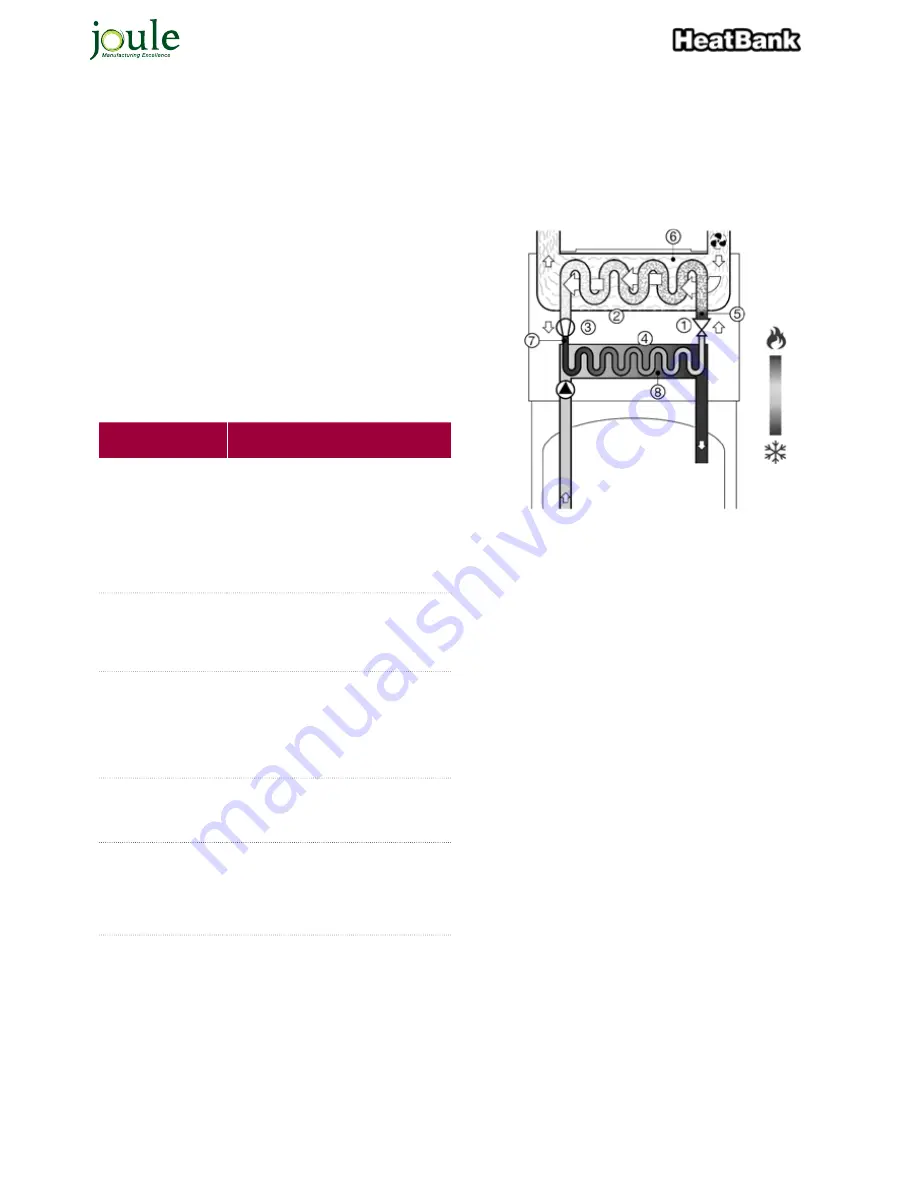
1.8 OPERATING PRINCIPLE OF THE VENTILATION
HEAT PUMP WATER HEATER
The Ventilation Heat Pump Water heater consists of an expansion
valve (1), an air heat exchanger (2), a compressor (3) and a water heat
exchanger (4).
A refrigerant circulates in the closed system (5). In the expansion valve,
the pressure and temperature of the refrigerant are lowered, which
becomes vaporous. It extracts heat from the air (6) via the air heat
exchanger . The vapour is then compressed
by the compressor . This increases the pressure and the temperature
(7). The heat is transferred to the water via the water heat exchanger
(8). And the cycle begins anew. It is therefore possible to heat water
with a low temperature of 10 °C to domestic hot water with a tem-
perature of 60 °C. This makes it possible to create four parts of energy
(heat) from just one part of energy (electricity).
10
ENG
Installation and user manual
1.7 OPERATING PRINCIPLE OF THE VENTILATION HEAT PUMP WATER HEATER
The Ventilation Heat Pump Water heater consists
of an expansion valve (1), an air heat exchanger (2),
a compressor (3) and a water heat exchanger (4).
A refrigerant circulates in the closed system (5). In
the expansion valve, the pressure and temperature
of the refrigerant are lowered, which becomes
vaporous. It extracts heat from the air (6) via the air
heat exchanger. The vapour is then compressed
by the compressor. This increases the pressure
and the temperature (7). The heat is transferred to
the water via the water heat exchanger (8). And the
cycle begins anew. It is therefore possible to heat
water with a low temperature of 10 ºC to domestic
hot water with a temperature of 60 ºC. This makes
it possible to create four parts of energy (heat) from
just one part of energy (electricity).
Configurations which
are not allowed
Consequences
Connection to the attic
or loft space .
When the insulation between the house and
the attic is not sufficient, through this con-
nection the loss of heat may increase . There
is also the possibility that a growing of mois-
ture will happen at the ceiling of the rooms
which are directly below the attic . There is
a chance that objects will fall or dust will be
drawn in by the VHW . This may reduce the
lifetime for the VHW .
The supply of air from
a heated room by the
VHW .
The air which is drawn by the VHW is al-
ready warmed by another heating source
in the system . In this situation the great-
est benefit of the VHW (the transmitting of
‘free’ energy into heat) is not used.
Connection to the me-
chanical ventilation .
he volume of air required by the VHW isn’t
suitable (380 / 490 m/h) for the volume of
air in a mechanical ventilation (which is
100 m/u). Furthermore the vapor of grease
and dust in the ducts of the mechanical
ventilation can circulate through and that
may cause a shorter lifetime for the VHW .
Making of a housing
around the air outside or
a repulsion of fresh air
inside .
This will cause a big loss in the coefficient
of performance and a strong cooling in the
room .
Connection to a ground
heat exchanger .
• Friction losses.
• Problems with the symmetrisation of
the two fans inside the ground heat ex-
changer .
• The evaporator will likely become
clogged .
Not allowed
• Make a ventilation connection with a dryer.
• Install in dusty room.
• Take air in which contains solvents and / or explosive substances.
• Connect the VHW to an extractor fan wich drains oily and contami-
nated air .
• Install the VHW in a room where there is a change of frost.
• Install the VHW on top of the boiler.
• Install in an atmosphere which is chlorinated (e.g. a swimming
pool) or fluorinated. • Install nearby sea areas or chemical plant
• Dusty air intake.


