


8
139587_05 GF 200 DV IPI October 2015
Vent Restriction
The GF 200 DV IPI is equipped with an Exhaust Restrictor
Plate which enables you to regulate the flow of exhaust
gas. The plate prevents overly strong draft that can
cause poor combustion and weak flame picture.
Follow
the guidelines below, and on the following pages, to
determine the correct restrictor plate setting for your
particular installation configuration.
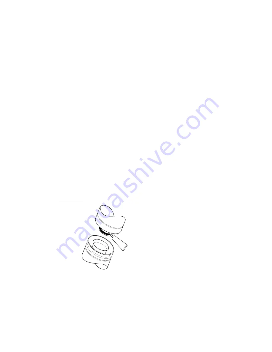
Exhaust Restrictor
The Exhaust Restrictor is an adjustable shutter located
within the firebox exhaust outlet. It is adjusted by moving
a pivot pin from the factory-set, fully OPEN (no restriction)
to fully CLOSED, (full restriction ). The Minus and Plus
signs on the dial relate to degrees of restriction, from less
to more. See Fig. 8. The five lettered positions correlate to
the termination zones (A,B,C,D,E) diagramed in figure 9.
Use the diagram to determine the degree of restriction
and shutter setting you should use.
Adjusting Exhaust Restrictor Plate:
1. Use the Vent Termination Matrix to determine which
setting position to use.
2. Lift the Top Plate from the stove.
3. Locate the restrictor adjustment dial on the top of the
exhaust outlet. Use a 1/4” nut driver to loosen the lock
nut and pivot the dial to the position appropriate to
your termination zone. See figs. 8 and 9.
4. Tighten the lock nut and replace the Top Plate.
Venting Requirements
The Jøtul GF 200 DV IPI gas stove may be installed with
a vertical or horizontal termination and must conform to
the configuration requirements described below.
This appliance is approved for use with vent systems
from the following manufacturers:
• M&G DuraVent, Inc. (Direct Vent Pro Series)
• American Metal Products (Amerivent)
• Security Chimneys International, Ltd. (Secure Vent)
• Selkirk Metalbestos (Direct Temp)
• Metal-Fab, Inc. (Direct Vent)
• Industrial Chimney Corp. (ExcelDirect)
• Bernard Dalsin Mfg. (Pro Form)
Use parts of one manufacturer only - DO NOT MIX
VENT COMPONENTS FROM DIFFERENT MANUFACTURERS
IN THE SAME SYSTEM.
Installation of any components not manufactured
or approved by Jøtul or failure to meet all clearance
requirements will void all warranties and could result in
property damage, bodily injury, or serious fire.
The approved vent configurations described
in this manual are derived from extensive testing
under controlled laboratory conditions. Gas appliance
performance can be negatively affected by variables
present in the installation environment, i.e: atmospheric
pressure, strong prevailing winds, adjacent structures and
trees, snow accumulation, etc. These conditions should be
taken into consideration by the installer and stove owner
when planning the vent system design.
IMPORTANT
• JOINT SEALING REQUIREMENT:
APPLY A 1/8” BEAD OF HIGH-
TEMPERATURE SEALANT
OR MIL-PAC® TO THE MALE
SECTION OF THE INNER VENT
PIPE. THE CEMENT SHOULD
FORM A SEAL BETWEEN THE
INNER AND OUTER PIPES.
• NEVER MODIFY ANY
VENTING COMPONENT,
OR USE ANY DAMAGED
VENTING PRODUCT.
• THE GAS APPLIANCE AND
VENT SYSTEM MUST BE
VENTED DIRECTLY TO THE
OUTSIDE OF THE BUILDING AND NEVER ATTACHED TO
A CHIMNEY SERVING A SOLID FUEL OR GAS BURNING
APPLIANCE. EACH DIRECT VENT GAS APPLIANCE MUST
HAVE ITS OWN SEPARATE VENT SYSTEM. COMMON
VENT SYSTEMS ARE PROHIBITED.
• IF VENTING SYSTEM IS DISASSEMBLED FOR ANY
REASON, REINSTALL PER THE INSTRUCTIONS PROVIDED
FOR THE INITIAL INSTALLATION.
Figure 7.
Approved Horizontal
and Vertical Vent Terminations
• Up to four 45° or two 90° elbows are permitted
in addition to the starter elbow. A horizontal run,
however, must be reduced by 5 feet for each additional
elbow, whether 45° or 90°.
•
NOTE: Long vent runs (over 12 ft.) in uninsulated air
space may require operation in CPI mode for best
performance.
• ALL VENTING MUST TERMINATE (END) WITHIN ONE OF
THE DESIGNATED AREAS.
• SET STOVE EXHAUST RESTRICTOR TO THE POSITION
THAT CORRESPONDS TO THE VENT TERMINATION
AREA IN THE MATRIX. When termination is exactly
on a division line, use the less restrictive position.
For example, if termination is at 11 ft./3ft., restriction
should be set at Position D.
The circled letter designations in the vent matrix in
figure 9 correspond to the Exhaust Restrictor dial settings
on the stove. First, determine which vent termination
zone is appropriate for your installation, then adjust the
restrictor to the corresponding position as shown in figure 9.