Section 2: Installation
Section 2: Installation
2.1 Alarm Controller Installation
Installing the iotega consists of connecting and powering up the hardware, as well as configuring the device using the
installer portal.
A typical installation includes the following steps:
1. Install the hardware
2. Create an account for the panel
3. Assign a service plan
4. Add a gateway
5. Create a master contact
6. Enroll sensors and other devices
7. Select Go Live on the Accounts: Summary page to bring the iotega online.
8. Test panel operation
To install the iotega:
1. Locate the panel on a flat surface in close proximity to AC power and a wireless router.
2. Remove the plastic pull tab from the access cover on the back of the panel to activate the battery. If the battery is not
installed, see Installing a new Battery.
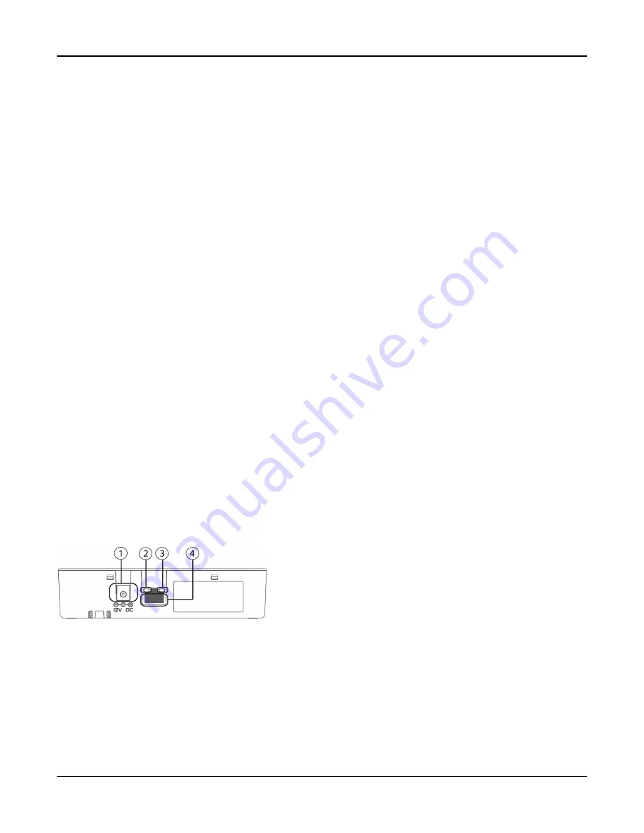
3. Connect the Ethernet cable to the port on the back of the panel. Connect the other end of the cable to the wireless
router.
4. Connect the barrel jack of the plug-in adapter to the power connector on the back of the panel. Route the power
cable through the strain relief channel on the bottom of the panel then plug the adapter into an AC outlet. The iotega
powers up once connected to AC.
The power-up sequence is as follows:
l
The integrated keypad numbers illuminate in sequence until power-up is complete.
l
The system powers up after approximately 2 minutes.
l
The Ethernet Link Speed LED illuminates steady green and the Ethernet Link Activity LED flashes rapidly to
indicate that a connection is being made to the network.
l
After several minutes, depending on network speed, the Remote Connection LED illuminates steady green,
indicating that a connection has been established.
Note:
If the Remote Connection Status LED flashes red, the panel may be having difficulty connecting to the remote
servers. Restarting the panel may remedy the issue.
For more information on LED indicators, see "Controls and Indicators" on page 8.
Note:
The following UDP ports must be open: 1234, 1235, and 1236. If the problem persists, contact technical support.
Figure 2-1 Panel Connections
1. Power Connector
2. Ethernet Link Speed LED
3. Ethernet Link Activity LED
4. Ethernet Port
- 6 -


