-
11
-
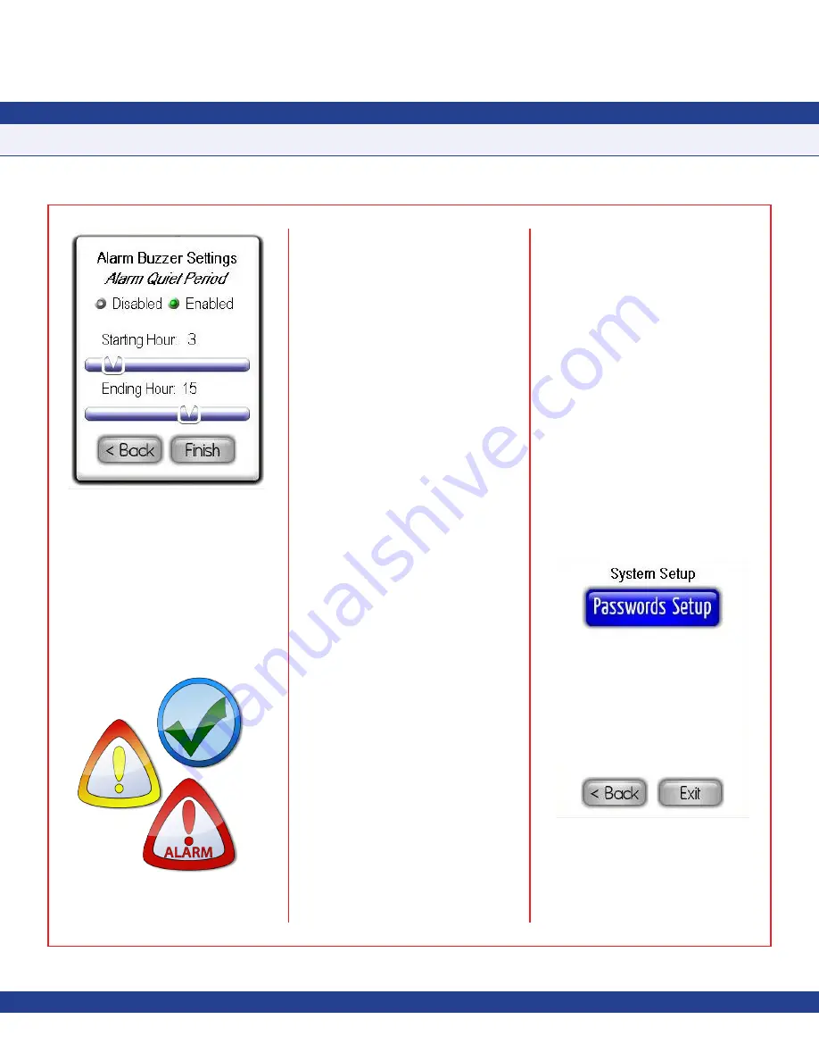
There are three alarm status conditions, each
represented by a distinct background color
and action icon on the display as shown in
Figure 20
.
There are also two additional action icons that
represent
Neutral
and
Auto-clean
mode at the
companion FMS-1655 controller.
Normal
status indicates that the monitored
parameter is within its normal operating
range and is indicated by a green background
and a green checkmark action icon. The
Safety Halo™ status indicator, if enabled,
will illuminate in green to indicate the
Normal
status.
Warning
status indicates that the monitored
parameter has drifted outside of its normal
operating range, but has not yet exceeded
the alarm setpoints. This condition is
indicated by a yellow background and a
yellow exclamation point action icon. The
Safety Halo™ status indicator, if enabled, will
flash slowly in yellow to indicate the warning
or caution status. This
Warning
status is
also used to indicate that a monitored door
associated with the differential pressure input
at an FMS-1655 is open.
Alarm
status indication that the monitored
parameter has exceeded the defined alarm
limits and is in need of attention. This critical
condition is indicated by a red background
and a red exclamation point action icon. The
Safety Halo™ status indicator, if enabled,
will flash quickly in red to indicate the
Alarm
status.
A blue background indicates that
Neutral
isolation mode is selected at the companion
FMS-1655. This mode is indicated by an
action icon represented as a red circle with
a line through its center. The Safety Halo™
status indicator, if enabled, will illuminate in
blue to indicate the
Neutral
isolation mode.
When
Auto-clean
mode at the companion
FMS-1655 is enabled, the FMS-1655R
indicates the status by a cyan background
and a simulated fan as the action icon. The
Safety Halo™ status indicator, if enabled, will
flash slowly in cyan to indicate that
Auto-clean
mode is active at the companion FMS-1655.
The next section discusses the option
available on the
System Setup
menu.
System Setup
To preserve the integrity of the configuration
settings stored in the non-volatile memory of
the FMS-1655R, a system security password
management facility has been incorporated
with a capacity of ten unique passwords.
The
System Setup
menu shown in
Figure
21
provides support for managing system
security passwords.
PROGRAMMING MANUAL
Fig. 19 Alarm Quiet Period
Fig. 20 Action icons
Fig. 21 System Setup


