


32
Jetter AG
Electrical installation – 2-cable technology
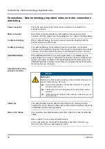
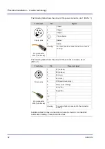
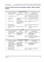
The following table shows the pinout of the power connector, size 1 (M23 x 1):
Front view
Pin
Signal
5
2
4
6
1
3
1
Phase 1
5
Phase 2
2
Phase 3
PE conductor
6-pole, pins
6
Brake+
Plug connector
M23 (with thread)
4
Brake-
Housing
The outer shield is connected to the connector
housing.
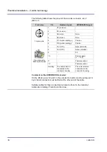
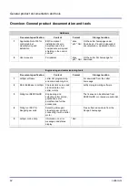
The following table shows the pinout of the encoder connector, size 1
(M23 x 1):
Front view
Pin
Resolver signal
12
9
11
5
7
8
6
4
10 2
1
3
12-pole, pins
1
S1 ()
2
S3 (cosine-)
3
S4 (sine-)
4
S2 (sine+)
5
R1R (exciter )
6
R2L (exciter winding-)
7
Th1 (PTC)
Plug connector
M23 (with thread)
8
Th2 (PTC)
9
-
10
-
11
-
12
-
Housing
The outer shield is connected to the connector
housing.
Suitable cables for these connectors can also be found in the Industrial
Automation Catalog, Products and Services.
Summary of Contents for JHN Series
Page 1: ...Installation Manual JHN JHQ and JL Servo Motors 60881738 We automate your success...
Page 6: ......
Page 43: ......


