3-3. Operation tips and sound pressure: Speed
Selection
Open pulley case and check if spindle speed
min-1or/min (R.P.M.) is correct for your job.
Drill
m/m
Recommended
Material
Cast Iron
Steel Iron Aluminium
Alloy
Copper
Ø
2 4780 2390 1275 635 3980 1910 7960 3980 4460 2230
Ø
3 3185 1590 850
425 2650 1275 5310 2655 2970 1485
Ø
4 2390 1195 640
320 1990 955 3980 1990 2230 1115
Ø
5 1910 955
510
255 1590 765 3185 1590 1785 890
Ø
6 1590 795
425
210 1330 640 2655 1330 1485 745
Ø
7 1365 680
365
180
1140 545 2275 1140 1275 635
Ø
8
1195
600
320
160
995
480 1990 995
1115
555
Ø
9 1060 530
285
140
885
425 1770 885
990
495
Ø
10 955
480
255
125
800
380 1590 800
890
445
Ø
11
870
435
230
115
725
350 1450 725
910
405
Ø
12 795
400
210
105
665
320 1330 665
745
370
Ø
13 735
365
195
100
610
295 1225 610
685
340
Ø
14 680
340
180
90
570
270
1135
570
635
320
Ø
15 640
320
170
85
530
255 1060 530
600
300
Ø
16 600
300
160
80
500
240
995
500
560
280
Ø
17 560
280
150
75
470
225
935
470
525
260
Ø
18 530
265
140
70
440
210
885
440
495
250
Ø
19 500
250
135
67
420
200
835
420
470
235
Ø
20 480
240
130
65
400
190
795
400
445
225
Ø
25 380
190
100
50
320
155
640
320
355
180
Ø
30 320
160
85
45
265
130
530
265
300
150
Ø
40 240
120
65
30
200
95
400
200
225
110
note
Processing is adjustable on the cutting materials as well as the
material of the cutting to real cutting conditions.
A- weighted sound pressure level measuring under
no load
Drilling-series
Operator position
Lpa= 62 dB(A)
A- weighted sound pressure level measuring under
load
Drilling- series
Operator position
Lpa= 64 dB(A)
378VBC
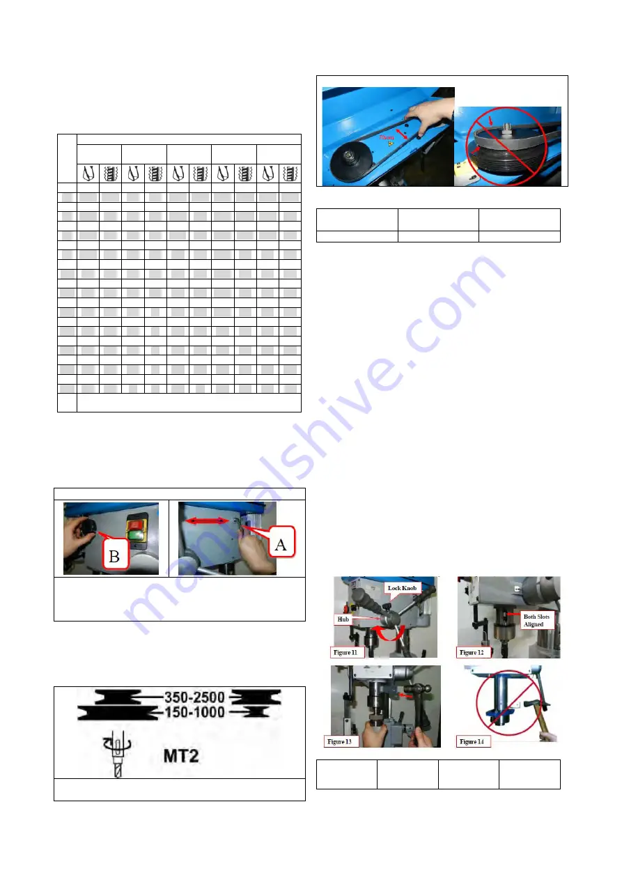
1. Loosen knob B on both sides of headstock.
2. Push handle A forward as arrow sign to get belt
tension.
3. Lock knob B firmly to fix belt tension.
When speed change is required. Loosen lead bolt (parts
no. 22-S2) on both side of headstock. Pull belt handle
(parts no. 26) to allow belts repositioning and then move
belts to correct groove to acquire desired speed. See
following speed chart for reference.
For proper belt tension, use 10 1bs pressure or hand
pressure on the belt as shown as bellow. The
recommended distance is about 70mm.
Models belt model tables
Machine model
Belt
specifications
Quantity
378VBC
6PJ 430
1
3-4. Withdraw drill bit :
The arbor can be removed to install another drill chuck in
the spindle. A drift key is included to help remove the
arbor from the spindle. Usually, once the chuck and
arbor have been properly mounted together, they are
considered semi-permanent connections.
(If you would like to install a different chuck, we
recommend getting a new arbor for that chuck.)
To remove the drill chuck and arbor:
1. Unplug the drill press!
2. Rotate the spindle handles until the drift-key slot is
exposed in the side of the quill.
3. Loosen the lock knob and rotate the hub (Figure 11)
clockwise until it stops.
4. Tighten the lock knob. The quill should not return up
into the head casting.
5. Rotate the spindle until the inner drift-key slot is
aligned with the outer slot, as shown in (Figure 12).
You will see through the spindle when the slot is
properly aligned.
6. Insert the drift key into the drift-key slot.
7. Tap the drift key with a rubber or wooden mallet, as
shown in (Figure 13), until the chuck releases.
8. Hold a downfeed handle with one hand, and loosen
the lock knob with the other hand.
9. Carefully retract the quill into the headstock.
10. Don't push spindle stroke too long to avoid spindle
stick. (Figure 14)
Hub
Figure 11
Figure 13
Lock Knob
Figure 12
Both Slots
Aligned
Figure 14
7


