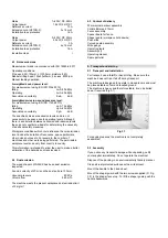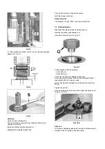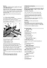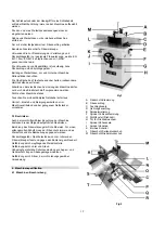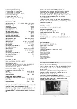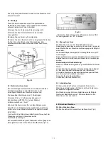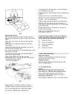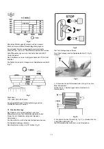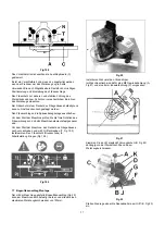
Fig 20
Install the curved guard body first.
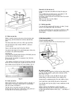
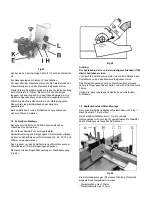
The machine table is therefore prepared with a M8 tapped
hole (A, Fig 21) and an 8mm pinhole (P).
Fig 21
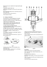
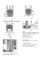
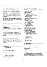
Set the height of the guide plate (B, Fig 22) depending on the
position and diameter of the tool and the thickness of the
workpiece. This part guides the wood and must always be
above the cutter.
Fig 22
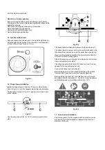
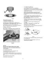
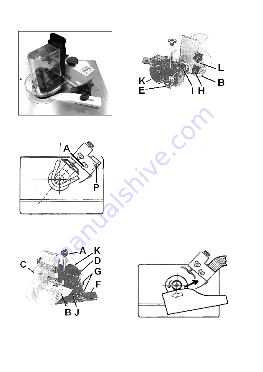
Use knob (E, Fig 23) to set the chip removal.
Fig 23
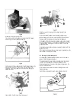
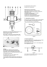
Slide the cover (C) down until it touches the part to be
machined.
Connect the dust collector to the curved guard port (K).
Before starting work, check manually that the cutter rotates
freely and that all components are correctly clamped.
At the start of the cut, move the workpiece along the straight
part of the guide plate (F). This way the workpiece enters the
cutter gradually, reaching the maximum depth of cut at the
guide plate mark.
Continue by moving the workpiece, keeping it aligned with the
guide plate mark.
When working complex shapes, make jigs and guides to guide
the workpiece properly and safely.
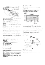
7.8 Sanding spindle installation
The optionaly available sanding spindle can be mounted in
place of the 30mm spindle arbour.
The sanding spindle may only be installed when the spindle
rotation lock is engaged and the mains plug is pulled.
Sanding sleeves and drums can be chosen between dia. 25,
38, 50, 75 and 100mm.
Cover the clearance zone around the sanding sleeve with
table insert rings.
Install the curved guard body for dust collection (Fig 24).
Fig 24
Summary of Contents for JWS-34KX
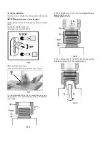
Page 44: ...A 1 A 2 A 3 A 4 A 5 ...

