14
9.4
Miter cuts
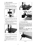
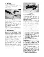
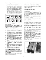
1. Loosen handle (G, Figure 17).
2. Rotate bow to desired angle up to 45-degrees,
using scale indicator on front of base.
3. Tighten
handle.
Figure 17
The angle scale is sufficient for most mitering
operations. If greater precision is needed, verify
setting with a protractor.
If handle (G) movement is obstructed, lift up on
handle and rotate it on the pin. Release handle,
making sure it seats itself properly on pin.
Bow should be returned to 90-
degree cut angle before lifting into vertical
position. See
section 7.5.
9.5
Setting feed rate
The feed rate of the blade into the workpiece is
important to band saw performance. Excessive
pressure of blade against the workpiece may break
the blade or stall the saw. In contrast, insufficient
pressure rapidly dulls the blade.
The hydraulic cylinder resists movement of the bow
in the downward direction. It offers no resistance
when the bow is raised upward.
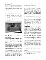
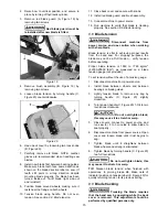
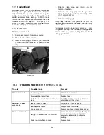
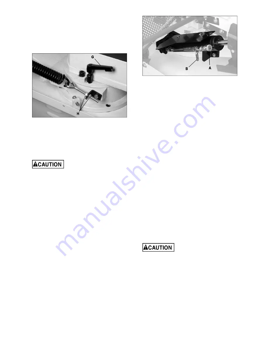
To increase feed rate, turn dial (A, Figure 18)
counterclockwise. To decrease, turn clockwise.
To close hydraulic flow, turn lever (B) down,
perpendicular to cylinder, as shown in Figure 18.
To open hydraulic flow, raise lever (B) parallel to
cylinder.
Feed rate is adjusted by the operator until the saw
is operating efficiently; usually determined by
observing chip formation. See
section 11.4,
Evaluating cutting efficiency.
Figure 18
9.6
Counterbalance spring
The counterbalance spring helps control the
amount of weight the saw bow puts on the
workpiece when the hydraulic control valve is fully
open. The hydraulic cylinder will not compensate
for improper counterbalance.
If the spring is not set properly, one can expect
poor performance, crooked cuts, tooth stripping,
stalling, and/or the blade running off the wheels.
Spring tension has been set by the manufacturer,
and should not require adjustment. If future
problems arise, indicating improper counter
balance, adjust spring as follows:
1. Disconnect machine from power source.
2. Turn ON hydraulic cylinder valve and place
saw bow in horizontal position.
3. Turn feed rate valve on hydraulic cylinder
counterclockwise until it stops.
4. Place a weigh scale (such as a spring or
hanging scale) beneath blade tension handle,
and lift saw bow. Scale should indicate
approximately 5 to 6 kg (11-13 lb).
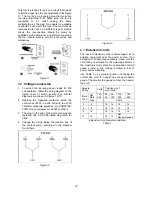
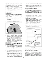
5. If adjustment is needed, loosen one nut and
tighten the other (H, Figure 17) on the eye bolt,
until scale indicates 5 to 6 kg.
9.7
Blade installation/replacement
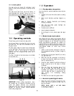
This band saw is designed for
use with blades that are 3/4" wide by 0.032”
thick x 93” long. Use of blades with different
specification may cause inferior performance.
A general-use variable-tooth blade is provided with
this band saw.
The choice of blade pitch is governed by the
thickness of the work to be cut: the thinner the
workpiece, the more teeth advised. A minimum of
three teeth should engage the workpiece at all
times. If the teeth of the blade are so far apart that
they straddle the work, severe damage to the
workpiece and to the blade can result.
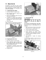
1. Disconnect machine from power source.
Summary of Contents for HVBS-710G
Page 23: ...23 14 1 1 HVBS 710SG Table and Stand Assembly Exploded View...
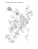
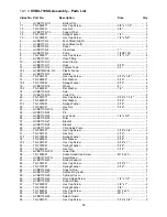
Page 24: ...24 14 1 2 HVBS 710SG Bow Assembly Exploded View...
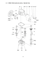
Page 29: ...29 14 2 1 HVBS 710SG Gearbox Assembly Exploded View...
Page 31: ...31 15 0 Electrical Connections for HVBS 710SG...
Page 32: ...32 427 New Sanford Road LaVergne Tennessee 37086 Phone 800 274 6848 www jettools com...


