16
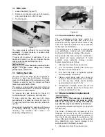
Blade tracking has been tested at the factory.
Adjustment is rarely required when the blade is
used properly and if the blade is correctly welded.
If a tracking problem occurs, first inspect blade
condition, then adjust tracking as follows:
1. Raise bow to vertical position and secure by
turning off hydraulic cylinder valve.
2. The blade should be properly tensioned. Refer
to
section 9.8 Blade tension.
3. Open back cover.
While performing the following
steps, keep the blade from rubbing excessively
on wheel flange. Excess rubbing will damage
wheel and/or blade.
4. Start saw and observe blade movement. Blade
should run next to, but not tightly against,
wheel flange.
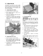
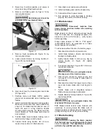
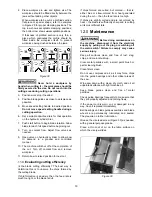
5. If blade will not track in position, loosen
screws (F, Figure 21), but do not remove.
Figure 21
6. Turn set screw (G, Figure 21) counter-
clockwise so that blade starts to move away
from the flange; then immediately turn set
screw in the other direction so that blade
stops, then moves slowly back toward flange.
NOTE: This adjustment is sensitive; do it
gradually and in small increments allowing the
wheel to respond to the changes.
Keep fingers clear of blade
and wheel to avoid injury.
7. Turn set screw to stop shifting of blade on the
wheel as it gets closer to wheel flange. Put a
six-inch length of paper between blade and
wheel. The paper should not be cut as it
passes between wheel flange and blade.
8. Turn set screw a small amount. Repeat the
insertion of paper between wheel flange and
blade until paper is cut into two pieces.
NOTE: You may have to repeat the check with
the paper several times before the blade and
the flange cut the paper into two pieces. Do
not hurry the adjustment. Patience and
accuracy here will pay off with better, more
accurate, quieter cutting and longer machine
and blade life.
9. When the paper is cut, back off the set screw
slightly. This assures that the blade is not
touching the flange of the wheel.
10. Tighten two screws (F, Figure 21).
9.10
Test cutting to verify adjustment
Test cuts can be used to determine whether or not
you have adjusted the blade accurately. Use 2-inch
round bar stock to perform these test cuts, as
follows:
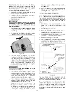
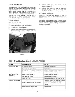
1. With bar stock securely clamped in the vise,
make a cut through the bar stock. (See Figure
22.)
2. Mark the top of the bar stock.
3. Move the bar stock about 1/4-inch past the
blade so that you can begin a second cut.
4. Rotate the bar stock 180 degrees so the mark
you made is now at the bottom of the cut.
5. Make a cut through the bar stock.
6. Use a micrometer to measure the thickness
variation of the disk you have cut from the bar
stock. Measure at top and bottom of disk.
Figure 22
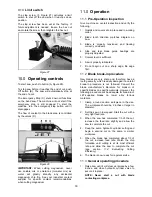
The saw blade can be considered correctly
adjusted when the variation measure is no more
than 0.012 inch across the face of the disk.
If you do not have a piece of 2-inch bar stock
available for a test cut, use a larger diameter test
piece rather than a smaller one. The maximum
thickness variation on any test piece should be no
more than 0.003 inch, per side, per inch of stock
diameter.
Summary of Contents for HVBS-710G
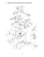
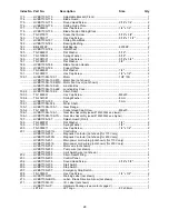
Page 23: ...23 14 1 1 HVBS 710SG Table and Stand Assembly Exploded View...
Page 24: ...24 14 1 2 HVBS 710SG Bow Assembly Exploded View...
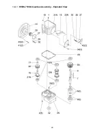
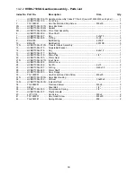
Page 29: ...29 14 2 1 HVBS 710SG Gearbox Assembly Exploded View...
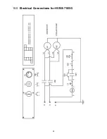
Page 31: ...31 15 0 Electrical Connections for HVBS 710SG...
Page 32: ...32 427 New Sanford Road LaVergne Tennessee 37086 Phone 800 274 6848 www jettools com...

