9
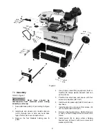
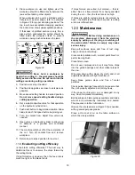
Figure 4
7.3
Assembly
Refer to Figure 4.
Band Saw should be
disconnected from electrical power during
assembly and setup.
1. Assemble base parts (J,K) according to Figure
4.
2. Install axle and wheels (H,
I
). Install cotter pin
(HP-9) through hole in axle, and bend back
legs of cotter pin to secure each wheel.
3. Remove the four brackets holding saw to
pallet.
4. Use properly rated lifting equipment (hoist or
forklift) with straps placed beneath cast iron
portion of saw.
5. Position saw atop base and secure with four
screws and washers (HP-1/6/7).
6. Install work stop assembly (A/B/C) into hole on
saw base.
7. Install handle (G), and place filter screen (D)
over coolant drain hole in pan.
8. Remove shipping bracket (x). Retain this piece
in case you must transport the machine in the
future.
9. Install guard (E) in place where shipping
bracket was removed, with two screws and
washers (HP-2/3/4).
Summary of Contents for HVBS-710G
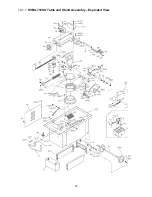
Page 23: ...23 14 1 1 HVBS 710SG Table and Stand Assembly Exploded View...
Page 24: ...24 14 1 2 HVBS 710SG Bow Assembly Exploded View...
Page 29: ...29 14 2 1 HVBS 710SG Gearbox Assembly Exploded View...
Page 31: ...31 15 0 Electrical Connections for HVBS 710SG...
Page 32: ...32 427 New Sanford Road LaVergne Tennessee 37086 Phone 800 274 6848 www jettools com...


