19
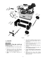
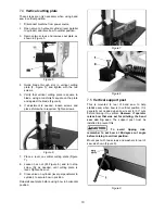
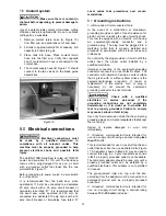
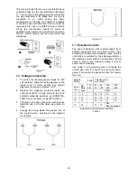
2. Place workpiece in vise and tighten vise. The
workpiece should be fitted directly between the
jaws without adding other objects.
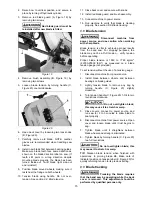
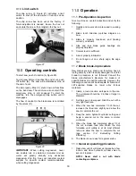
When workpiece to be cut is a profiled section,
flat piece or special shape, refer to examples
in Figure 29 for proper clamping positions. The
top row shows acceptable clamping positions;
the bottom row shows
un
acceptable positions.
If thickness of profiled section is very thin, a
piece which duplicates the profile should be
fitted inside the workpiece itself, to prevent
workpiece being crushed between the jaws.
Figure 29
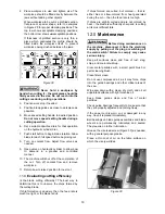
Never hold a workpiece by
hand when cutting it – the workpiece should be
firmly secured in the vise. Do not reach into the
cutting area during cutting operations.
3. Position work stop if needed.
4. Position blade guides as close to workpiece as
possible.
5. Move speed setting handle to desired position.
Do not move speed setting handle during a
cutting operation.
6. Set a suitable downfeed rate for that operation
on the hydraulic cylinder dial.
7. Push start button to begin blade rotation. Allow
blade to reach full speed before beginning cut.
8. Turn on coolant flow. Adjust flow valves as
needed.
9. Open valve on hydraulic cylinder to allow bow
to descend in a gradual and controlled
manner.
10. The machine will shut off at the completion of
the cut. Turn off coolant flow and remove
workpiece.
11. Return bow to raised position for next cut.
11.4
Evaluating cutting efficiency
Is the blade cutting efficiently? The best way to
determine this is to observe the chips formed by
the cutting blade.
If chip formation is powdery, then the feed rate is
much too light, or the blade is dull.
If chips formed are curled, but colored — that is,
either blue or straw-colored from heat generated
during the cut — then the feed rate is too high.
If chips are slightly curled and are not colored by
heat – the blade is sufficiently sharp and is cutting
at its most efficient rate.
12.0
Maintenance
Before doing maintenance on
the machine, disconnect it from the electrical
supply by pulling out the plug or switching off
the main switch! Failure to comply may cause
serious injury.
Keep all surfaces clean and free of rust, slag,
chips, and coolant build-up.
Clear metal particles with a small paint brush or
parts cleaning brush.
Clean filter screen.
Do not use compressed air, as it may force chips
into the guide bearings and other critical areas of
the saw.
Wipe saw down with a clean, dry cloth, and oil all
unpainted surfaces with light machine oil.
Keep blade guides clean and free of metal
particles.
Check guide bearings frequently to make sure that
they are properly adjusted and turning freely.
If the power cord is worn, cut, or damaged in any
way, have it replaced immediately.
Ball bearings on blade guide assemblies and blade
wheels are permanently lubricated and sealed.
They require no further lubrication.
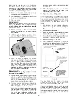
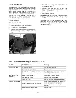
Grease the vise lead screw (Figure 30) as needed,
with a general purpose grease.
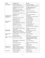
Place a thin coat of oil on the table surface on
which the vise jaw slides.
Figure 30
Summary of Contents for HVBS-710G
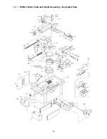
Page 23: ...23 14 1 1 HVBS 710SG Table and Stand Assembly Exploded View...
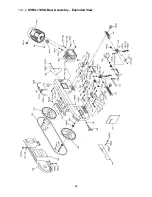
Page 24: ...24 14 1 2 HVBS 710SG Bow Assembly Exploded View...
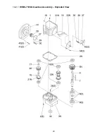
Page 29: ...29 14 2 1 HVBS 710SG Gearbox Assembly Exploded View...
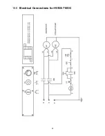
Page 31: ...31 15 0 Electrical Connections for HVBS 710SG...
Page 32: ...32 427 New Sanford Road LaVergne Tennessee 37086 Phone 800 274 6848 www jettools com...

