background image


1.0

  Warranty and Service 

JET warrants every product it sells against manufacturers’ defects. If one of our tools needs service or repair, please 
contact


Technical Service by calling 1-800-274-6846, 8AM to 5PM CST, Monday through Friday. 

Warranty Period


The general warranty lasts for the time period specified in the literature included with your product or on the official JET 
branded website.  


JET products carry a limited warranty which varies in duration based upon the product. (See chart below) 


Accessories carry a limited warranty of one year from the date of receipt. 


Consumable items are defined as expendable parts or accessories expected to become inoperable within a 
reasonable amount of use and are covered by a 90 day limited warranty against manufacturer’s defects. 

Who is Covered 

This warranty covers only the initial purchaser of the product from the date of delivery. 

What is Covered 

This warranty covers any defects in workmanship or materials subject to the limitations stated below. This warranty does 
not cover failures due directly or indirectly to misuse, abuse, negligence or accidents, normal wear-and-tear, improper 
repair, alterations or lack of maintenance. JET woodworking machinery is designed to be used with Wood. Use of these 
machines in the processing of metal, plastics, or other materials outside recommended guidelines may void the warranty. 
The exceptions are acrylics and other natural items that are made specifically for wood turning. 

Warranty Limitations 

Woodworking products with a Five Year Warranty that are used for commercial or industrial purposes default to a Two 
Year Warranty. Please contact Technical Service at 1-800-274-6846 for further clarification.


How to Get Technical Support 

Please contact Technical Service by calling 1-800-274-6846. 

Please note that you will be asked to provide proof of 

initial purchase when calling. 

If a product requires further inspection, the Technical Service representative will explain 

and assist with any additional action needed.


JET has Authorized Service Centers located throughout the United States. 

For the name of an Authorized Service Center in your area call 1-800-274-6846 or use the Service Center Locator on the 
JET website.


More Information 

JET is constantly adding new products. For complete, up-to-date product information, check with your local distributor or 
visit the JET website. 

How State Law Applies 

This warranty gives you specific legal rights, subject to applicable state law.  

Limitations on This Warranty 

JET LIMITS ALL IMPLIED WARRANTIES TO THE PERIOD OF THE LIMITED WARRANTY FOR EACH PRODUCT. 
EXCEPT AS STATED HEREIN, ANY IMPLIED WARRANTIES OF MERCHANTABILITY AND FITNESS FOR A 
PARTICULAR PURPOSE ARE EXCLUDED. SOME STATES DO NOT ALLOW LIMITATIONS ON HOW LONG AN 
IMPLIED WARRANTY LASTS, SO THE ABOVE LIMITATION MAY NOT APPLY TO YOU. 
 
JET SHALL IN NO EVENT BE LIABLE FOR DEATH, INJURIES TO PERSONS OR PROPERTY, OR FOR INCIDENTAL, 
CONTINGENT, SPECIAL, OR CONSEQUENTIAL DAMAGES ARISING FROM THE USE OF OUR PRODUCTS. SOME 
STATES DO NOT ALLOW THE EXCLUSION OR LIMITATION OF INCIDENTAL OR CONSEQUENTIAL DAMAGES, SO 
THE ABOVE LIMITATION OR EXCLUSION MAY NOT APPLY TO YOU. 
 
JET sells through distributors only. The specifications listed in JET printed materials and on official JET website are given 
as general information and are not binding. JET reserves the right to effect at any time, without prior notice, those 
alterations to parts, fittings, and accessory equipment which they may deem necessary for any reason whatsoever. JET

®


branded products are not sold in Canada by JPW Industries, Inc. 

Product Listing with Warranty Period  

90 Days – Parts; Consumable items 
1 Year – Motors; Machine Accessories; Heavy 
2 Year – Metalworking Machinery; Electric Hoists, Electric Hoist Accessories; Woodworking Machinery used 
for industrial or commercial purposes 
5 Year – Woodworking Machinery 
Limited Lifetime – JET Parallel clamps; VOLT Series Electric Hoists; Manual Hoists; Manual Hoist   
Accessories; Shop Tools; Warehouse & Dock products; Hand Tools; Air Tools 

 
NOTE:  JET is a division of JPW Industries, Inc. References in this document to JET also apply to JPW Industries, Inc., or 
any of its successors in interest to the JET brand. 


Summary of Contents for HVBS-710G

Page 1: ...Manual 7x10 inch Gear Head Mitering Band Saw Model HVBS 710SG JET 427 New Sanford Road LaVergne Tennessee 37086 Part No M 413452 Ph 800 274 6848 Revision C3 01 2021 www jettools com Copyright 2016 JET...

Page 2: ...al action needed JET has Authorized Service Centers located throughout the United States For the name of an Authorized Service Center in your area call 1 800 274 6846 or use the Service Center Locator...

Page 3: ...9 7 Blade installation replacement 14 9 8 Blade tension 15 9 9 Blade tracking 15 9 10 Test cutting to verify adjustment 16 9 11 Setting blade speed 17 9 12 Blade guide adjustment 17 9 13 Chip brush 1...

Page 4: ...nance is complete 15 Make sure workpiece is securely clamped in the vise Never use your hand to hold the workpiece 16 Check coolant level frequently Replace dirty or weak coolant 17 Check damaged part...

Page 5: ...always make personal safety a priority If there are questions or comments please contact your local supplier or JET JET can also be reached at our web site www jettools com Retain this manual for fut...

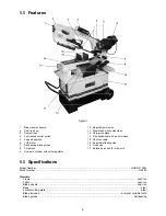
Page 6: ...e work stop 11 Steel stand with coolant tank 12 Chip guide plate 13 Vise handwheel with quick release 14 Cast iron table 15 Adjustable floating vise 16 Fixed vise 17 Rotating disc hub for miter cuts 6...

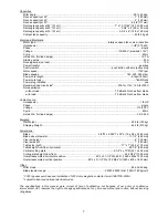
Page 7: ...mp Horsepower 1 8 HP Phase single Voltage 115 230 V Cycle 60Hz Listed FLA full load amps 0 5 0 25 A Weights Net Weight 396 lb 180 kg Shipping Weight 462 lb 210 kg Dimensions Blade 3 4 W x 0 035 T x 93...

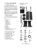
Page 8: ...f you do not see a part below check the machine some parts may have come pre assembled to the saw Refer to Figures 2 and 3 1 Band Saw 1 Workstop bar A 1 Workstop B 1 Workstop rod C 1 Filter screen D 1...

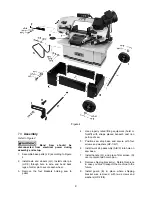
Page 9: ...ng saw to pallet 4 Use properly rated lifting equipment hoist or forklift with straps placed beneath cast iron portion of saw 5 Position saw atop base and secure with four screws and washers HP 1 6 7...

Page 10: ...ace a level on vertical cutting plate Figure 7 8 Loosen hex nut M Figure 8 and turn stop screw N as needed until cutting plate is level Tighten hex nut 9 Close valve on cylinder lever perpendicular to...

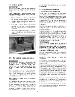
Page 11: ...ic shock This tool is equipped with an electric cord having an equipment grounding conductor and a grounding plug The plug must be plugged into a matching outlet that is properly installed and grounde...

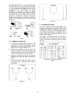
Page 12: ...th the 230V contactor separate purchase p n HVBS710S 250N See your dealer or call JET to order 3 The plug on the end of the motor cord must be replaced with a UL CSA listed plug rated for 240V 4 Chang...

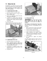
Page 13: ...bed against the blade and the fixed vise jaw The square should lie along entire length of jaw and blade without a gap 3 If adjustment is necessary loosen screws holding vise C Figure 15 and shift vise...

Page 14: ...the amount of weight the saw bow puts on the workpiece when the hydraulic control valve is fully open The hydraulic cylinder will not compensate for improper counterbalance If the spring is not set p...

Page 15: ...king with sharp blade Blade tension is vital to achieving proper results from the band saw For shipping purposes the blade may not be at full tension verify tension before operating Proper blade tensi...

Page 16: ...Repeat the insertion of paper between wheel flange and blade until paper is cut into two pieces NOTE You may have to repeat the check with the paper several times before the blade and the flange cut t...

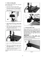
Page 17: ...ill still turn freely with this clearance If the clearance is incorrect the blade may track off the drive wheel 1 Disconnect machine from power source 2 Raise bow to vertical and secure in place by tu...

Page 18: ...correctly on wheels 4 Side and rear blade guide bearings are properly adjusted 5 Coolant level is sufficient 6 Saw is properly lubricated 7 Do not begin cut on a sharp edge file edge first 11 2 Blade...

Page 19: ...luating cutting efficiency Is the blade cutting efficiently The best way to determine this is to observe the chips formed by the cutting blade If chip formation is powdery then the feed rate is much t...

Page 20: ...90W oil 6 Reinstall vent plug B Completely drain and refill gear box oil after the first 90 days of operation Thereafter change every six months Periodically after draining remove screws cover and gas...

Page 21: ...e rubs on wheel flange Adjust blade tracking Teeth too coarse for material Use appropriate blade for material being cut Teeth in contact with workpiece before saw is started Start motor before blade c...

Page 22: ...hrough Friday 8 00 a m to 5 00 p m CST Having the Model Number and Serial Number of your machine available when you call will allow us to serve you quickly and accurately Non proprietary parts such as...

Page 23: ...23 14 1 1 HVBS 710SG Table and Stand Assembly Exploded View...

Page 24: ...24 14 1 2 HVBS 710SG Bow Assembly Exploded View...

Page 25: ...031 Flat Washer 5 16 8 21 1 TS 0720081 Spring Washer 5 16 4 22 TS 0561021 Hex Nut 5 16 4 23 HVBS710S 23G Door 1 24 HVBS710S 24 Pin 2 25 HVBS710S 25 Lock Knob 1 4 x 3 4 1 26 HVBS710S 26 Filter 1 27 HVB...

Page 26: ...ey 5 x 20mm 1 86 HVBS710S 86 Lead Screw Bracket 1 87 HVBS710S 87 Acme Nut 1 88 HVBS710S 88 Button 1 89 HVBS710S 89 Retainer 1 90 TS 2361051 Spring Washer M5 1 91 HVBS710S 91 Round Head Screw M5 x 8 1...

Page 27: ...Bearing Pin 8 mm 2 144 HVBS710S 144 Adjustable Blade Seat Rear 1 144 1 HVBS710S 144 1 Adjustable Blade Seat Front 1 145 TS 0561032 Hex Nut 3 8 24UNF 4 145 1 TS 0720091 Spring Washer 3 8 4 146 HVBS710...

Page 28: ...er 8 mm 2 193 HVBS710S 193 Key 5 mm 1 194 1 HVBS710SG 328 Worm Shaft 1 195 1 HVBS710SG 195 1 Gear Flange 1 195 2 TS 1503051 Socket Head Cap Screw M6x20 1 196 1 HVBS710SG 196 1 Gear Box Assembly serial...

Page 29: ...29 14 2 1 HVBS 710SG Gearbox Assembly Exploded View...

Page 30: ...HVBS710SG 315 Adjustable Bracket 1 16 HVBS710SG 316 Key 6x6x12 1 17 HVBS710SG 317 Bushing 1 18 HVBS710SG 318 Drain Plug 1 4 1 20 HVBS710SG 320 Worm Gear 1 21N HVBS710SG 321N Input Gear 1 24 HVBS710SG...

Page 31: ...31 15 0 Electrical Connections for HVBS 710SG...

Page 32: ...32 427 New Sanford Road LaVergne Tennessee 37086 Phone 800 274 6848 www jettools com...

Reviews: