


User Manual ECOSTEP®54
24
Subject to change without notice!
6.5
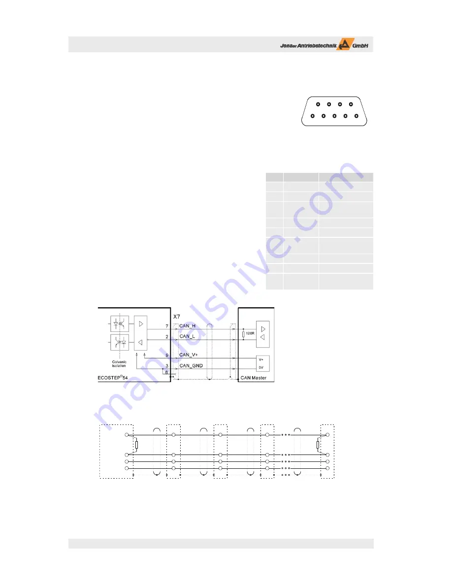
X7: CAN interface
Die CAN interface of the ECOSTEP®54 is based on the communication profi le
CiA DS 301 and the device profi le CiA DSP 402 (drives and motion control).
It must be supplied with an external voltage.
Terminating resistors for busses are not built in the ECOSTEP®54. A CAN bus
has to be terminated with a 120 Ω resistor at the beginning and at the end. If
the ECOSTEP®54 is operated as fi rst or last participant at a CAN bus, it is use-
ful to solder the terminating resistor in the mating connector of X7 between
the pins 2 and 7.
Th e manual „Object Dictionary ECOVARIO® and ECOSTEP®“
contains a detailed description of all available functions.
Th e Baud rate und the device ID can be set via the
appropriate CAN objects. By default the ID is set to 1.
Th e following baud rates are supported: 1 000 kBit/s, 500 kBit/s,
250 kBit/s, 125 kBit/s, 100 kBit/s, 50 kBit/s. If point of sampling
and scan rate (86.7 %, 3-times sampling at all Baud rates) do not
meet the demands please get in touch with the technical service
of Jenaer Antriebstechnik.
6
7
8
9
1
2
3
4
5
Fig. 6.15: Mating connector X7:
9-pole D-Sub socket; View of
the solder or crimp side
Pin
Signal
Description
1
-
n.c.
2
CAN_L
CAN data L
3
CAN_GND
reference potential
to CAN data
4
-
n.c.
5
-
n.c.
6
CAN_GND
reference potential
to CAN_V+
7
CAN_H
CAN data H
8
-
n.c.
9
CAN_V+
+8 ... + 18 VDC,
max. 50 mA
Table 6.8: Pin assignment connector X7
Fig. 6.16: Circuit X7 CAN interface
Fig. 6.17: Dimensioning terminating resistors R depending on line impedance; default: R = 120 Ω
CAN_V+
CAN_GND
CAN_L
CAN_H
7
2
9
3
7
9
3
7
2
9
3
7
2
9
3
2
Master in
CAN-Bus
X7
Axis 1-4
X7
X7
X7
Axis 5-8
Axis 9-12
Axis n
R
R