


Subject to change without notice!
User Manual ECOSTEP®54
13
4.4
General technical data
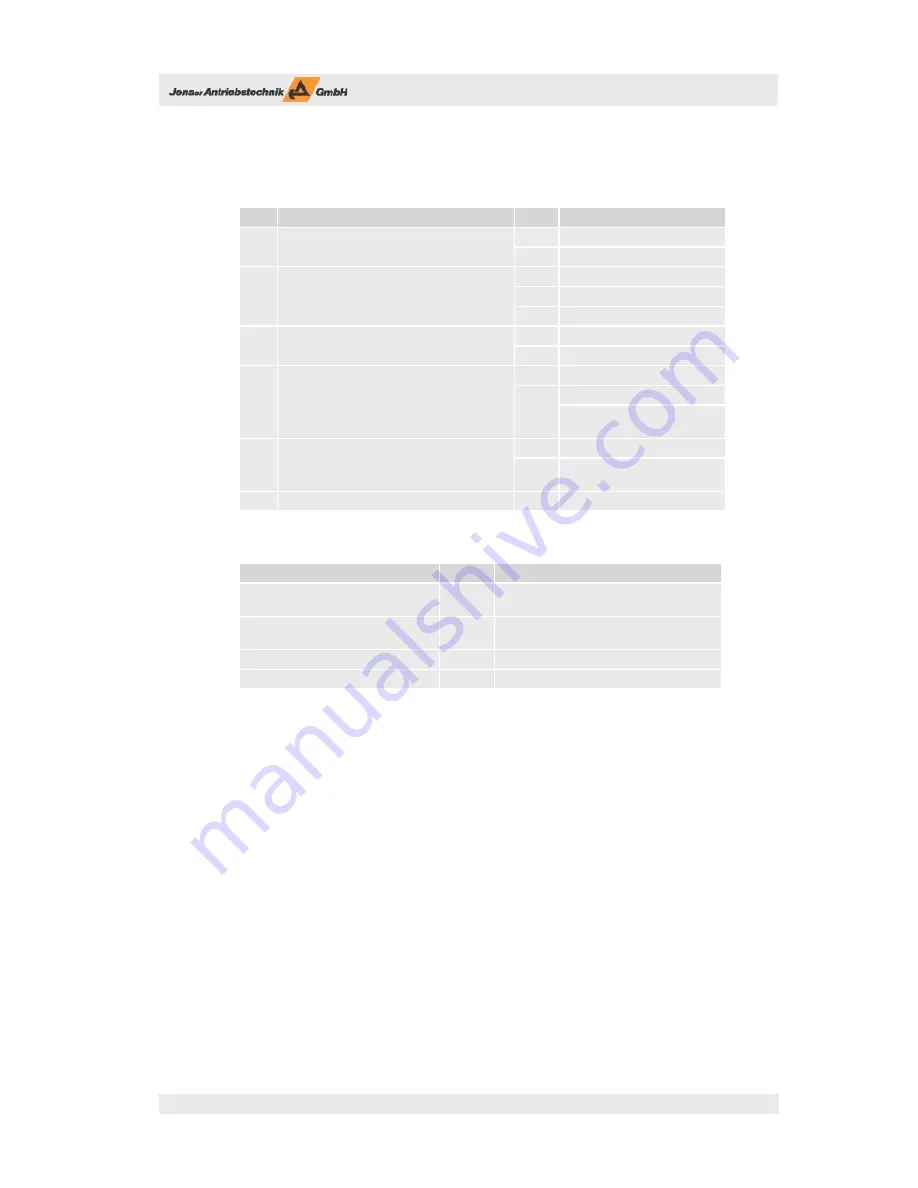
Table 4.4: General technical data: control signals
No.
Control signal
Unit
1
24 V supply (current draw without outputs)
V
DC
24 ±10 %
A
0.8
8
Digital control signal inputs
(user-programmable,
or as limit switch inputs)
V
DC
LOW 0 – 4, HIGH 13 – 30
mA
3.4 / 2.4 (at 24 V
DC
)
kΩ
7
1
Control signal DC link relay (REL+, REL-)
V
DC
20 ... 24
mA
50
8
Digital control signal outputs
(4 user-programmable,
4 resereved for holding brakes)
V
DC
24 (20 ... 30)
A
0.5
Holding brake: max. 0.8 / 0.4 A
(100 ms / continuous)
4
Analog inputs
0 V ... +5 V, 10 bit resolution
kΩ
at DC: R > 250
at f > 250 Hz: R < 15
1
Analog output
-10 V – +10 V, 8 bit resolution
Table 4.5: General technical data: dimensions and weight
Dimensions and weight
Unit
Dimensions without heat sink
(w x h x d)
mm
240 x 62 x 170 (without mating connector)
Dimensions with heat sink
(w x h x d)
mm
240 x 102 x 170 (without mating connector)
Weight (without heat sink)
kg
1.8 kg
Weight (with heat sink)
kg
3.4 kg
4.5
Modes for setpoint setting
ECOSTEP®54 provides the following modes for setpoint setting:
Online positioning via fi eld bus (RS232, CANopen)
Positioning control via SPS interface (digital inputs/outputs)
Joystick operation (analog inputs, resolution 10 bit).
4.6
Suitable types of motors
With ECOSTEP®54 stepper motor amplifi er various types of stepper motors can be operated, among others
the stepper motor series 17S und 23S of Jenaer Antriebstechnik GmbH. Technical data and regulations in
this manual only refer to these motors. Technical data of the motors can be retrieved from the motor data
sheets or from our homepage www.jat-gmbh.de.