JDS Uniphase OLP-85 User Manual Download Page 43

OLP-85

43

D

ISPLAYING


STORED


RESULTS

7  M

EMORY

 M

ANAGEMENT

4.

Press the 

[

G

]

 key again every time you want to save a an 

additional result value.

The display briefly shows the Fiber ID used.

Notes:

If the 

Fiber ID

 is not changed, the data set will be saved 

under the same title. Depending on the active 

application, the 

Data & Reports

 can be distinguished by 

the 

Timestamp

 or a five-digit sequential number. The 

Fiber ID 

can be sorted using the timestamp.

Displaying stored results

To display the last results stored:

The homescreen is displayed.

1.

Press the 

[

A

]

 key.

2.

Tap the 

[

Data

]

 button.

A selection of the available applications is displayed.

3.

Tap the desired application button.

– or –

The instrument is in application mode.

1.

Press the 

[

A

]

 key.

2.

Tap the 

[

More

]

 button.

3.

Tap the 

[

Data

]

 button.

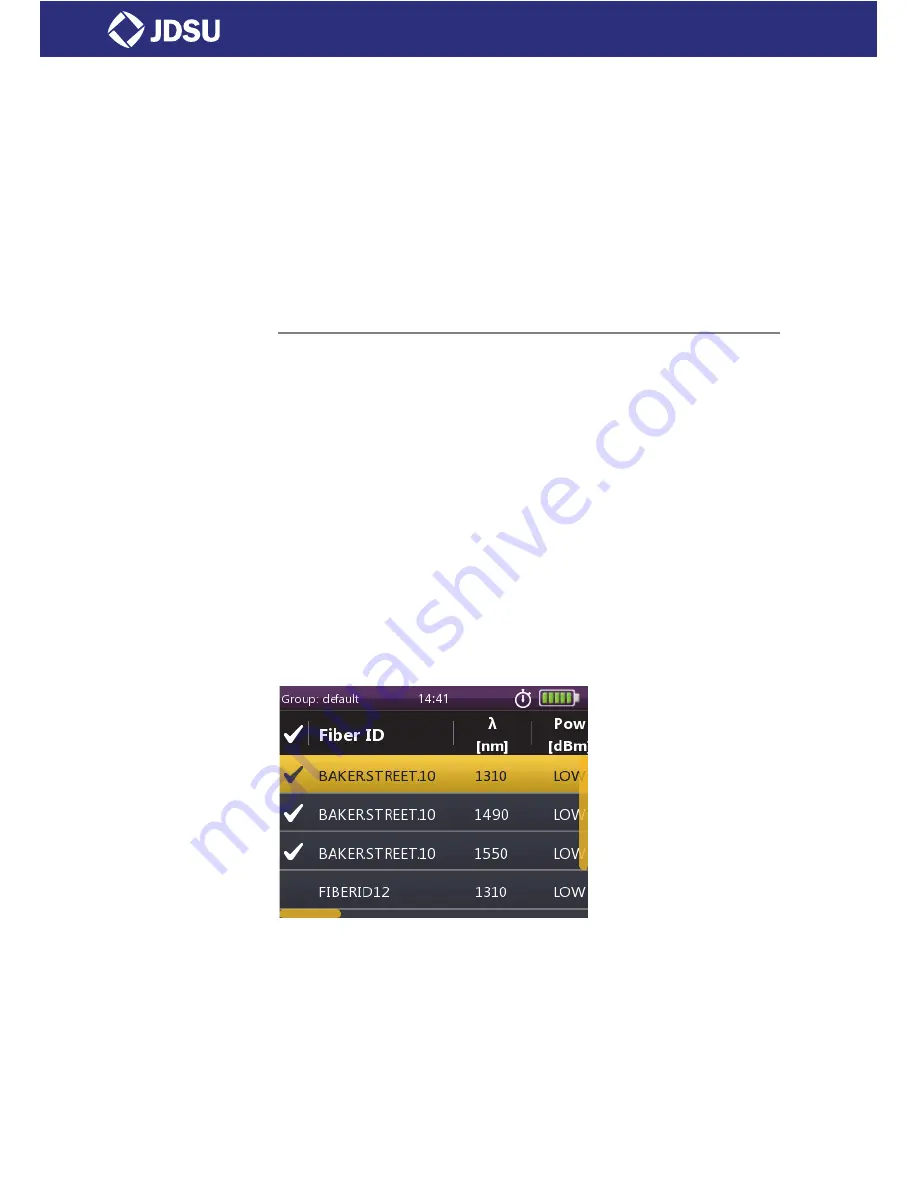
The measurement data of the currently selected group is 

displayed:

To display the last results stored in Probe mode:

The homescreen is displayed.

1.

Tap the 

[

Data

]

 button.

2.

Tap the 

[

Probe

]

 button.

Measurement data of the currently selected group is displayed.

Summary of Contents for OLP-85

Page 1: ......

Page 2: ...oduct includes Qt 4 8 3 software licensed under the GNU LGPL v 2 1 and barebox 2012 02 0 and linux 3 1 0 rc8 software licensed under the GNU GPL v 3 To request a copy of the source code for this softw...

Page 3: ...ables 19 BASIC OPERATION 20 Switching the instrument on off 20 Operator control panel 20 Display elements 21 Navigating in the menus 22 Configuring the instrument 22 Software options 26 PROBE PCM OPER...

Page 4: ...k Data Mode 44 Clearing the memory 46 MAINTENANCE 47 Cleaning the test port 47 Cleaning the instrument 48 REMOTE CONTROL 49 Communication interface 49 Command parameters and responses 52 Commands 53 E...

Page 5: ...easurement data can be summarized within a professional industry standard test report Battery operation from AA dry cells or from a rechargeable Li Ion Battery Pack ensure long operating time in the f...

Page 6: ...utomatic wavelength detection This application requires a wavelength encoding light source e g one of the OLS 85 Optical Light Sources Operating manual update Continuing enhancement and further develo...

Page 7: ...the instructions carefully to avoid a low or medium risk of injury to persons WARNING Follow the instructions carefully to avoid servere injury to persons DANGER Follow the instructions carefully to...

Page 8: ...e g Select mode Italics Result Indicates the result of following an instruction e g The page opens Boldface Pages controls and display elements Screen pages controls and display elements are indicate...

Page 9: ...se make sure the instrument is not operated outside the permitted ambient conditions Always make sure that the instrument is in proper working order before switching it on Warning symbols indicating a...

Page 10: ...ment the output of a laser source or an optical fiber connected to a source or a system Always cover unused ports Be aware that the emitted light is not visible Heed the normal precautions for working...

Page 11: ...g the instrument NOTICE Ambient temperature too high low Temperatures outside the operating range of 0 to 40 C can damage the PS4 Universal AC DC Power Supply or adversely affect its function and safe...

Page 12: ...C Power Supply or adversely affect its function and safety Do not operate the PS4 Universal AC DC Power Supply if condensation has formed If condensation cannot be avoided such as when the PS4 Univers...

Page 13: ...aged during shipping This is particularly likely if the packaging is visibly damaged If there is damage do not attempt to operate the instrument Doing so can cause further damage In case of damage ple...

Page 14: ...ls focus control automated Pass Fail analysis magnification control 3 Connector interface 4 Test head cover 5 3 5 inch touchscreen 6 Key pad operator control panel 7 Battery compartment and stand on r...

Page 15: ...sources can be used to operate the OLP 85 Eight 1 5 V dry batteries Mignon AA size alkaline type recommended Eight 1 2 V NiMH rechargeable batteries Mignon AA size no internal charge PS4 Universal AC...

Page 16: ...ries correctly The correct polarity is indicated by a diagram inside the battery compartment or WARNING Dangers when handling batteries Handling batteries may be dangerous Please note the following sa...

Page 17: ...S4 Universal AC DC Power Supply and the USB interface are both connected General tips on using batteries Always handle batteries with care Do not drop or damage the batteries or expose them to excessi...

Page 18: ...ollecting such waste or for recycling please make use of these rather than throwing the batteries in with normal trash You will often be able to return used batteries to the place where you purchase n...

Page 19: ...s under the cover on the right side 2 Plug the PS4 into the AC line socket The OLP 85 switches on automatically when powered from the PS4 Notes The PS4 provides power even if dry or rechargeable batte...

Page 20: ...o the homescreen Press to open menu Press to go back within an application or cancel input Press to toggle between the inspect view and the test view Press to switch the instrument on and off LED glow...

Page 21: ...power supply The OLP 85 is powered by the external AC adapter when this symbol is shown Battery status Indicates the battery charge status If it is not shown only the AC adapter is active Probe To vie...

Page 22: ...touchscreen To leave a menu without making any changes Press the F key Notes All actions can be operated via the operator control panel or the touchscreen The following instructions describe only touc...

Page 23: ...of the instrument texts Date Time To adjust the date date format time and to set 24 hour time or 12 hour time Date To adjust the date Date Format To adjust the date format Time To adjust the time Time...

Page 24: ...ton 3 Type in the desired brightness value 4 Tap the OK button Selecting a language 1 Press the A key and tap the Settings button 2 Tap the Language button The language menu opens 3 Tap the language y...

Page 25: ...key and tap the Settings button 2 Tap the Date Time button 3 Tap the Date button 4 To change the setting tap on the Hour Minute or Second button 5 Type in the desired value and tap the OK button 6 Tap...

Page 26: ...appears 3 Release the A key 4 Plug the USB flash drive into one of the instrument USB ports 5 To start the firmware update procedure press the center key within the arrow keys If the update procedure...

Page 27: ...ful installation or number of errors will be displayed in the following menu 7 Remove the USB flash drive To display the installed software options The software options are installed and the confirmat...

Page 28: ...using one of the OLP 85P models with an integrated PCM for patch cord inspection and a P5000i Digital Probe for bulkhead inspection Both applications Probe and PCM behave essentially the same and are...

Page 29: ...the bulkhead female and patch cord male sides of fiber connectors as well as other optical devices such as transceivers The Digital Probe is specially designed to fit and operate comfortably and easi...

Page 30: ...lkhead tips Fig 3 9 P5000i Digital Probe components FBPT series tips for the P5000i The P5000i Digital Probe uses FBPT series inspection tips to ensure consistent and accurate inspection for a wide va...

Page 31: ...different workflows the functionality of the QuickCapture key is configurable Pressing the key will either freeze the live image or start a test Camera mode Set the QuickCapture key on the Digital Pr...

Page 32: ...center key within the arrow keys Test mode Launching a test of the connector and fiber end face See Freeze mode on page 34 for more information on commands available To launch the test with the prede...

Page 33: ...ority of the fiber cladding Zone C represents the epoxy ring Zone D represents the ferrule zone it identifies a portion of the ferrule near and around the fiber Notes To return to a Live image press t...

Page 34: ...eypad enter the name of the JPG file 3 Press Enter to validate and save the document The file is saved in the current active group directory on the OLP 85 Freeze mode Once the image is acceptable shar...

Page 35: ...ail criteria for single mode APC connectors from IEC 61300 3 35 standard SM_PC Pass Fail criteria for single mode PC connectors from IEC 61300 3 35 standard MM_ Pass Fail criteria for multi mode conne...

Page 36: ...rd level Bear this in mind when using the OLP 85 Always be aware of the hazard level of the instrument to be connected Connect the optical fiber before switching on the radiation source Switch off the...

Page 37: ...t Wavelength menu is displayed 3 To select a wavelength tap a preselected wavelength Setting a wavelength in the table Show or hide wavelengths in the table The instrument is in Powermeter mode 1 Pres...

Page 38: ...Limit button 4 Type in the desired value 5 Tap the OK button Enabling Auto mode Auto is a special feature developed by JDSU that allows you to identify wavelengths automatically To do this the signal...

Page 39: ...signals The OLP 85 automatically detects the modulation frequency of light signals modulated at the fixed frequencies of 270 Hz 1 kHz and 2 kHz The detected frequency is shown in the lower right disp...

Page 40: ...erence level The actual power level is set as the new reference level The reference level is displayed underneath the wavelength Reference power level display mode is activated Notes The reference lev...

Page 41: ...matic incrementation AutoInc Index To define the starting point of numeric automatic incrementation Create Project To create a new project group Delete Project To delete the project currently displaye...

Page 42: ...yed Tip Depending on the active application the Data Reports can be distinguished by the Timestamp or a five digit sequential number Saving results Results are stored simply by pressing the G key Each...

Page 43: ...n be sorted using the timestamp Displaying stored results To display the last results stored The homescreen is displayed 1 Press the A key 2 Tap the Data button A selection of the available applicatio...

Page 44: ...he A key 2 Tap the More button 3 To generate a report from the measurement results tap the Reports button Notes For a project only one report be created Summarize data by using the Link Data Mode Seve...

Page 45: ...p the Link Data Mode button Project settings are shown grayed Link Data Mode is active 4 Press the F key to exit from the menu To changed the linked applications The homescreen is displayed 1 Press th...

Page 46: ...ject Clears all the measurements of the selected project Clearing memory data The Data Reports menu is displayed Press the A key To clear the data from a current measurement 1 Select the group and mea...

Page 47: ...Wipe off the plug end surface using a cotton bud soaked in isopropanol This cleaning method is very effective and leaves no residue 4 Blow out the test adapter with clean compressed air available in s...

Page 48: ...ets dirty through use you can clean it using a soft cloth moistened with a mild solution of detergent NOTICE Water and cleaning fluids The instrument may be damaged or destroyed if water or cleaning f...

Page 49: ...al operation The main purpose of the remote control capability of the SmartClass Fiber family is to set and get Setup and Result values from an application More complex remote control commands called...

Page 50: ...pplication In order to identify an application each application has a unique application ID app_ID which will be used to set the switch For example send APPM SEL SYSTEM in order to select the system a...

Page 51: ...by using the commands in the following table Notes Applications that are not currently visible will return 221 Settings conflict when setting a Setup that affects shared resources Results will return...

Page 52: ...nteger value Examples 23 90 0 NR2 Real number Examples 23 45 1 30 NR3 Exponential number Examples 4 3E 3 8 9456E8 123E 5 NRf NR1 NR2 NR3 BOOLEAN Boolean value If the setting range is used as a respons...

Page 53: ...3 COMMANDS 9 REMOTE CONTROL Commands Overview Generic commands These commands are always used without a prefix IDN OPT RST APPM LIST APPM SEL APPM SEL APPM VER SYST DATE SYST DATE SYST ERR SYST TIME S...

Page 54: ...NE A F INSP ZONE NUMB APP ID VSBL APP ID VSBL AUTO CNTR AUTO CNTR CAPT BTTN MODE CAPT BTTN MODE FQM ENAB FQM ENAB FRZE BUSY INSP BUSY INSP ERR INSP PRF NAME INSP PRF NAME INSP PRF NAMES INSP TBL SHOW...

Page 55: ...STOR NAMES STOR NOTE STOR NOTE STOR WR BUSY APP FACT DEF MICR CAL INFO MICR MODL NAME MICR SER NUMB MICR SW VER STOR ALL DEL STOR DEL STOR GRP CREA STOR GRP DEL STOR EVAL TYPE STOR RD STOR RD EVAL XML...

Page 56: ...LMBD AUTO LMBD AUTO LMBD DTCT EVAL ENAB1 EVAL ENAB 1 MEAS ACT SENS MEAS MODE SENS MEAS MODE SENS POW REF SENS POW REF SENS POW UNIT SENS POW UNIT SENS THRS PASS1 SENS THRS PASS 1 SENS WLEN SENS WLEN T...

Page 57: ...ended commands STOR GRP NAMES STOR NAMES STOR NOTE STOR NOTE STOR WR BUSY 1 Only available on instruments with separate optical broadband input SENS ABS TO REF STOR ALL DEL STOR DEL STOR DEL MLTP STOR...

Page 58: ...nded commands APP ID VSBL APP ID VSBL AUTO OFF AUTO OFF DISP BRGH DISP BRGH DISP OFF DISP OFF ETH MAC ADDR IP ADDR IP ADDR STAT IP ADDR STAT IP GATE IP GATE STAT IP GATE STAT IP MASK IP MASK STAT IP M...

Page 59: ...LP 85 59 COMMANDS 9 REMOTE CONTROL PowerManagement application These commands are used with the prefix PMGNT Results Setups Extended commands BATT CAP PERC BATT TYPE POW SPLY CON STOR AVLB APP FACT DE...

Page 60: ...rovides a list of application IDs separated by commas Response type STRING_RESPONSE_DATA APPM SEL STRING Selects the application specified by the application ID provided Valid values All application I...

Page 61: ...he image Response type NR1 FQM PERC MAX Focus quality highwater mark Highest focus quality value recently observed Response type NR1 INSP PASS Pass Fail result for the complete fiber Response type BOO...

Page 62: ...for more information AUTO CNTR BOOLEAN Controls fiber center tracking for live video images in high magnification mode Default TRUE AUTO CNTR Returns TRUE if the fiber center tracking in live video is...

Page 63: ...fault name See INSP PRF NAMES command for more information INSP PRF NAME Returns the name of the selected inspection profile Response type STRING See INSP PRF NAME command for more information INSP PR...

Page 64: ...of the Digital Probe is high Response type BOOLEAN See MAGN HIGH command for more information MICR BAD Returns TRUE if the detected Digital Probe could not be initialized properly Response type BOOLEA...

Page 65: ...t feature Valid range 1 to maximum integer Default 1 STOR AUTO INCR IDX Returns the current index for the automatic increment feature Response type NR1 See STOR AUTO INCR IDX command for more informat...

Page 66: ...pe Unit Info Command string Parameter type Response type Unit Info APP FACT DEF Sets all parameters of the application to their default values MICR CAL INFO Returns the list of calibrations tips of th...

Page 67: ...ntifier string3 STOR RD EVAL XML STRING STRING STRING Returns the contents of a pfr xml pfr pass fail result file specified by group string1 fiber identifier string2 and internal identifier string3 Sp...

Page 68: ...R WR BUSY returns 0 before proceeding This command creates up to seven files for up to seven components of the result The seven STOR RD queries are used to read these result files To create unique fil...

Page 69: ...NG See APP ID VSBL command for more information AUTO LMBD BOOLEAN Determines whether the instrument recognizes Auto modulation frequencies Default TRUE AUTO LMBD Returns TRUE if the instrument recogni...

Page 70: ...rmation SENS THRS PASS Sets the threshold value PASS for the actual wavelength unit dBm Default 01 SENS THRS PASS Returns the threshold value PASS in dBm Response type NR2 See SENS THRS PASS command f...

Page 71: ...USER NR1 User selectable wavelength This setup can always be changed It is copied to SENS WLEN if we are not in Auto mode The value is also added to the SENS WLEN TBL SENS WLEN USER Returns the user s...

Page 72: ...ES This setup contains the names of all available storage groups The default group is always available STOR NAMES This setup contains the fiber IDs and internal IDs belonging to the group specified by...

Page 73: ...identifiers string2 and a list of comma separated internal identifiers string3 e g STOR DEL MLTP TEST ID1 ID1 ID2 00005 00009 00001 STOR GRP CREA STRING Creates an empty storage group STOR GRP DEL ST...

Page 74: ...esponse type STRING See APP ID VSBL command for more information AUTO OFF NR1 Sets the time of inactivity after which the instrument automatically goes into standby mode If an external power supply is...

Page 75: ...valid for the instrument In static mode this setup corresponds to IP ADDR STAT in DHCP mode it is provided by the DHCP server This setup is read only IP ADDR STAT STRING Sets the static mode IP addre...

Page 76: ...if the IP address should be requested by DHCP or a static address should be used Valid values 0 STATIC 1 DHCP Default 1 IP MODE Returns whether the instrument is set to a static or dynamic IP address...

Page 77: ...ns a list of the software options installed via USB flash drive or a key The list is cleared at the beginning of each installation OPT ULCK Returns all installed software options STOR AVLB Returns whe...

Page 78: ...an internal battery NOBATT with a rechargeable Lithium Ion battery LIION or with standard dry cell batteries DRYCELL 0 No battery 1 Lithium Ion battery 2 Dry cell batteries POW SPLY CON 0 No external...

Page 79: ...stem error 350 Queue overflow 360 Communication error 100 Command error 101 Invalid character 108 Parameter not allowed 109 Missing parameter 110 Command header error 112 Program mnemonic too long 113...

Page 80: ...ries AA size Accessories Digital Analysis Microscope OLP 85 Power meter 800 1650 nm 75 to 26 dBm BN 2307 03 OLP 85P Power meter with integrated patch cord microscope 800 1650 nm 75 to 26 dBm BN 2308 0...

Page 81: ...01 dB 0 001 W Maximum level 800 nm to 1650 nm 30 dBm Intrinsic uncertainty1 1 Under reference conditions 20 dBm CW at calibrated wavelengths 1 nm 23 C 3K 9 m test fiber with SC PC ceramic connector 0...

Page 82: ...rface or Ethernet Remote control capability Via USB Electrical interfaces 2 USB Type A 1 USB Micro B Ethernet Power supply Four way power NiMH dry batteries RBP2 Li Ion Battery Pack PS4 Universal AC D...

Page 83: ...play elements 21 Displaying Modulated signals 39 Relative power level 40 E Environmental Management Program 85 Environmental protection 18 Extended commands 78 Powermeter 73 Probe PCM 66 System 77 F F...

Page 84: ...ds Error messages 79 Generic commands 60 PowerManagement 59 78 Powermeter 56 68 69 73 Probe PCM 54 61 62 66 System 58 74 77 Results PowerManagement 78 Powermeter 68 Probe PCM 61 RoHS 87 S Saving resul...

Page 85: ...cture Environmental restrictions and requirements are taken into account during planning and manufacture of JDSU products This attention ranges from the raw materials and finished components selected...

Page 86: ...ght of a crossed out trash can and a black bar This symbol can be found either on the device or in the accompanying documents Contact your local Technical Assistance Center TAC for return and collecti...

Page 87: ...he Chinese Market only RoHS PBDE O O O O O O PBB O O O O O O CR6 O O O O O O Cd O O O O O O Hg O O O O O O Pb X O O O O O Component Main Product PCB Assemblies Internal wiring Display Keyboard Plastic...

Page 88: ...88 OLP 85 ROHS...

Reviews: