background image

ENGLISH

OPERATION MANUAL

JB SYSTEMS®

7/55

LED MANAGER

Once the correct time is shown, press the ENTER button. The new clock settings are saved while the
display shows “time”

Remarks:

You can abort the setting procedure and go back without saving the changes by shortly pressing

the MENU button. When the setup is done and changes are saved, you can return to the clock display by
pressing the MENU button for more than 1second.

ON/OFF Timers “START-time” setting

The LED Manager has 3 individual ON/OFF timers. So you are able to switch the output on/off at 3 different
parts of the day, each time with a different color or color chase. Below we explain how to set the start-time
for “ON/OFF timer1”. The settings for the other 2 timers are identical.

Press the MENU button and UP/DOWN buttons until the display shows “t1on”

Press the ENTER button, the HOUR-display starts blinking.

Use the DOWN and UP buttons to set the correct hours (00 to 23).

Press the ENTER button, the MINUTE-display starts blinking.

Use the DOWN and UP buttons to set the correct minutes (00 to 59).

Once the correct start time is shown, press the ENTER button. The new start time is saved while the
display shows “t1on”

Remarks:

You can abort the setting procedure and go back without saving the changes by shortly pressing

the MENU button. When the setup is done and changes are saved, you can return to the clock display by
pressing the MENU button for more than 1second.

ON/OFF Timer “STOP-time” setting

Below we explain how to set the stop-time for “ON/OFF timer1”. The settings for the other 2 timers are
identical.

Press the MENU button and UP/DOWN buttons until the display shows “t1oF”

Press the ENTER button, the HOUR-display starts blinking.

Use the DOWN and UP buttons to set the correct hours (00 to 23).

Press the ENTER button, the MINUTE-display starts blinking.

Use the DOWN and UP buttons to set the correct minutes (00 to 59).

Once the correct stop time is shown, press the ENTER button. The new stop time is saved while the
display shows “t1oF”

Remarks:

You can abort the setting procedure and go back without saving the changes by shortly pressing

the MENU button. When the setup is done and changes are saved, you can return to the clock display by
pressing the MENU button for more than 1second.

ON/OFF Timer “SCENE” setting

Below we explain how to select the scene (color or color chase) for “ON/OFF timer1”. The settings for the
other 2 timers are identical.

Press the MENU button and UP/DOWN buttons until the display shows “t1rE”

Press the ENTER button, the display starts blinking.

Now you have the time to set the scene that you would like to reproduce when the timer is activated.

When the scene is OK (don’t forget to switch the blackout function off!) just press the ENTER button again.
The display stops blinking and the scene is saved.

Remarks:

You can abort the setting procedure and go back without saving the changes by shortly pressing

the MENU button. When the setup is done and changes are saved, you can return to the clock display by
pressing the MENU button for more than 1second.

OPERATING INSTRUCTIONS

A. Standalone 1unit:

Connect the LED projectors to the LED Manager as indicated in the previous chapters. (no need to set
a DMX address!)

Switch the unit on and refer to the chapter “Functions” to make yourself familiar with the various
functions of the faders and buttons.

In this mode you can also set the clock and use the 3 on/off timers as described in the previous chapter.

Remark:

When a timer is active, you can deactivate it by pressing the blackout button.

ENGLISH

OPERATION MANUAL

JB SYSTEMS®

8/55

LED MANAGER

B. Two or more units in master/slave setup:

Connect the LED projectors to the LED Managers as indicated in the previous chapters.

Connect the units with each other as explained in the chapter about electrical installations. (no need to
set a DMX address!

Switch the LED Managers on. You can only use the controls on the master unit, the controls on the
slaves are disabled. Refer to the chapter “Functions” to make yourself familiar with the various
functions of the faders and buttons on the master unit.

In this mode you can also set the clock and use the 3 on/off timers on the master as described in the
previous chapter.

Remark:

When a timer is active, you can deactivate it by pressing the blackoutbutton.

C. Connect the optional LEDCON-01 controller for remote control:

In most cases the LED MANAGER will be installed on a wall, close to the LED-projectors. If you want to
have easy access to its functions, you can connect the LEDCON-01 remote controller to the (first) LED
Manager. The other connections are identical to those of the standalone or master/slave setups.
Except for the display, internal 24H clock and the 3 on/off timers, the controls on the remote are identical
to that of the LED Manager. So please refer to the chapter “Functions” to make yourself familiar with the
various functions of the faders and buttons.

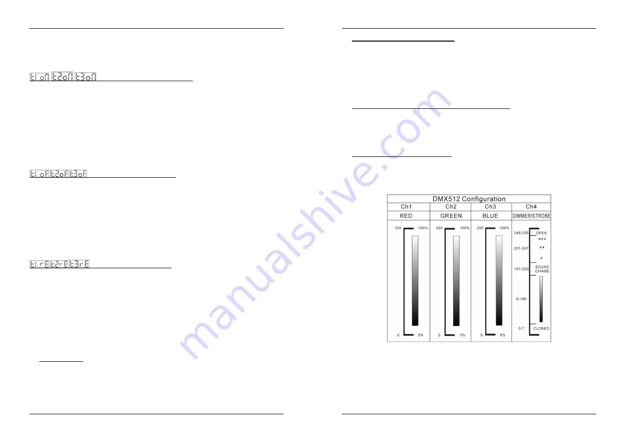
D. Controlled by universal DMX-controller:

Connect the LED projectors to the LED Manager(s) as indicated in the previous chapters.

Connect the LED Manager(s) with all other DMX-appliances in the DMX-chain.

Switch all units on and set the proper DMX-addresses. (DMX-LED on the LED Manager is lit)

Switch your universal DMX-controller on and refer to the DMX chart below to control the connected
LED managers:

All controls (buttons and faders) on the LED Manager(s) are disabled, except the buttons needed to set
the DMX-address.

Summary of Contents for led manager

Page 1: ...the content in any manner without express permission of the publisher is prohibited LED MANAGER DMX COMPATIBLE 300Watt LED POWER SUPPLY Version 1 2 Operation Manual Mode d emploi Gebruiksaanwijzing Be...

Page 2: ...t toestel en de gebruikte batterijen op een milieuvriendelijke manier conform de in uw land geldende voorschriften DU ENTSORGUNG DES GER TS Entsorgen Sie das Ger t und die Batterien auf umweltfreundli...

Page 3: ...ngle is intended to alert the use or the presence of un insulated dangerous voltage within the product s enclosure that may be of sufficient magnitude to constitute a risk of electric shock The exclam...

Page 4: ...G B ENGLISH OPERATION MANUAL JB SYSTEMS 4 55 LED MANAGER FUNCTIONS REAR 15 FIXING HOLES used to fix the unit on a wall or other flat surface 16 OUTPUT CABLES used to connect different 24Vdc common ano...

Page 5: ...s and battery backup To use the battery backup feature you must install 3 optional AA type NiMH rechargeable batteries Once these batteries are installed they will be recharged automatically no need t...

Page 6: ...when the timer is activated When the scene is OK don t forget to switch the blackout function off just press the ENTER button again The display stops blinking and the scene is saved Remarks You can ab...

Page 7: ...us des jolies transitions Vitesse et clairage r glables avec curseur Transition de couleur lente r glable avec curseur Fonctions Black out et full on Toutes les fonctions peuvent tre contr l es par le...

Page 8: ...ment un fusible endommag par un fusible de m me type et sp cifications lectriques En cas de probl mes de fonctionnement s rieux arr tez toute utilisation de l appareil et contactez votre revendeur imm...

Page 9: ...une rallonge de 1m avec connecteur 4pin m le femelles et d enlever le connecteur femelle Maintenant vous pouvez facilement d nuder le c ble Vous trouverez 4 fils color s l int rieur Fil blanc Le fil c...

Page 10: ...ts en appuyant nouveau bri vement la touche MENU Quand l installation est faite et les changements sont sauv s vous pouvez retourner l cran de l horloge en appuyant sur la touche MENU pendant plus d u...

Page 11: ...lier le contr leur avec la commande distance LEDCON 01 sur le premier LED MANAGER Les autres raccordements sont identiques l installation autonome ou l installation ma tre esclave Except l cran l horl...

Page 12: ...izing verwijderen Er bevinden zich geen onderdelen in het toestel die u zelf kan herstellen Laat de herstellingen enkel uitvoeren door een bevoegde technicus De bliksempijl die zich in een gelijkbenig...

Page 13: ...hases De rechtse kant van de fader wijst naar de verschillende kleuren Bijlangrijke opmerking Er is ook een functie color fade die heel mooi is voor achtergrondverlichting Selecteer deze functie om za...

Page 14: ...skabel doorlinken Vb JB Systems ref 7 0063 De eenheid met een vrije DMX input connector wordt automatisch master de Master LED is aan de andere apparaten worden automatisch geschakeld als slaves slave...

Page 15: ...n procedure annuleren en teruggaan zonder de veranderingen te bewaren door de MENU toets kort in te drukken Na het uitvoeren van de setup en het bewaren van de nieuwe waarden kan u naar de klok displa...

Page 16: ...t juiste DMX adres in de DMX LED op de LED Manager is aan Zet uw universele DMX controller aan en neem een kijkje op de DMX grafiek hieronder om de verbonden LED Managers te controleren Alle bediening...

Page 17: ...en Sie keines der Geh useteile Im Ger te inneren befinden sich keine vom Benutzer reparierbaren Teile berlassen Sie Reparaturen dem qualifizierten Kundendienst Das Blitzsymbol im Dreieck weist den Ben...

Page 18: ...TPUT MONITOR Zeigt die Ausgangspegel der 3 Farben an R G B DEUTSCH BEDIENUNGSANLEITUNG JB SYSTEMS 32 55 LED MANAGER FUNKTIONEN R CKSEITE 15 MONTAGEL CHER Befestigung des Ger ts an einer Wand oder eine...

Page 19: ...indern m ssen Sie die Kette mit einem 90 bis 120 Abschlusswiderstand am Ende abschlie en Benutzen Sie nie ein Y Kabel Jedes Ger t in der Kette ben tigt eine korrekte Startadresse damit es wei welche B...

Page 20: ...von mehr als 1 Sekunde auf die MENU Taste zur Uhrzeitanzeigezur ck DEUTSCH BEDIENUNGSANLEITUNG JB SYSTEMS 36 55 LED MANAGER EIN AUS Timer Einstellen einer SZENE Weiter unten wird erkl rt wie man eine...

Page 21: ...dio Spectrum mix 32 diversos colores spectrum mix incluyendo hermosas transici nes de color Velocidad y amortigue ajustable con los atenuadores Transition de color lento con transition de tiempo ajust...

Page 22: ...arato y contacte su vendedor inmediatamente Por favor use el embalaje original cuando el aparato deba ser transportado Debido a motivos de seguridad est prohibido de hacer modificaciones al aparato si...

Page 23: ...te el anillo de pl stico al conectador Ejemplo usted puede conectar la hastaquince 1m LED STRIP en cada cable de la salida total los 30m ESPA OL MANUAL DE INSTRUCCIONES JB SYSTEMS 42 55 LED MANAGER B...

Page 24: ...cador HORA empezar a parpadear Use DOWN y UP para establecer la hora correcta 00 a 23 Pulse ENTER el indicador MINUTOS empezar a parpadear Use DOWN y UP para establecer los minutos correctos 00 a 59 C...

Page 25: ...el controlador remoto LEDCON 01 al primer LED Manager Las dem s conexiones son id nticas a las de las configuraciones independientes o maestro esclavo Excepto por la pantalla el reloj 24H interno y l...

Page 26: ...en a de voltagem perigosa n o isolada no interior do produto que poder constituir risco de choque el ctrico O s mbolo composto por um tri ngulo equil tero com um ponto de exclama o alerta o utilizador...

Page 27: ...cores R G B a n vel zero 14 MONITOR DE SA DA Indica os n veis de sa da das 3 cores R G B PORTUGU S MANUAL DO UTILIZADOR JB SYSTEMS 50 55 LED MANAGER FUN ES TRASEIRA 15 BURACOS DE FIXA O utilizados pa...

Page 28: ...viduais e bateria de apoio Para usar a fun o de bateria de apoio tem de instalar 3 pilhas recarreg veis AA NiMH opcionais Assim que estas pilhas estiverem instaladas ir o ser recarregadas automaticame...

Page 29: ...e gostaria de reproduzir quando o temporizador activado Agora que a scene est OK n o se esque a de desligar a fun o blackout pressione apenas o bot o ENTER outra vez O ecr para de piscar e a scene gra...

Page 30: ...x 150W max Total 300W max o Vermelho 2x 50W max Total 100W max o Verde 2x 50W max Total 100W max o Azul 2x 50W max Total 100W max Liga es DMX XLR 3 pinos DMX 512 standard Canais DMX 4 CH1 vermelho CH2...

Reviews: