11
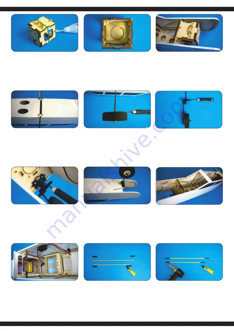
Incollare le parti F29 - F33 come mostrato sopra.
Use instant glue to secure F29-F33 in place with SF logo facing
top.
Quando la colla si è asciugata, ricoprire le parti F34 con la colla
e incollarle nel supporto motore per il rinforzo (vedi illustrazione).
When the glue is dried enough; spread some epoxy on F34 and
secure F34 inside the motor mount; spread some epoxy on the
corners of F34 for reinforcement.
Dopo che la colla si è asciugata, incollare il supporto motore nel-
la parte anteriore della fusoliera. Per il fissaggio, incollare una
F35 cada a destra e a sinistra del supporto motore.
When the glue is dried enough; install the motor mount inside the
head of fuselage, use instant glue to secure the motor mount in
place. Place F35 inside the motor mount and use epoxy to secu-
re it in place. Spread some epoxy on two sides of motor mount.
Avvitare il carrello di atterraggio del muso nel supporto del carrel-
lo di atterraggio nella parte anteriore della paratia, assicurandosi
che la capacità di sterzata non sia compromessa.
Install nose gear assembly into the nose gear mount, place a
collar on top of it and secure with M3x4mm hex screw. Install
nose gear assembly into the nose gear mount, place a collar on
top of it and secure with M3x4mm hex screw.
Rimuovere un‘asta filettata M2 x 450 mm, avvitare una testa
di forcella e far scorrere un piccolo pezzo di tubo in silicone
sull‘asta filettata. Agganciare la forcella nella parte anteriore del
timone del carrello.
Take on piece of M2 x 450mm rod out of the hardware bag;
screw in clevis on one end; slide in a small piece of silicon tube,
pull the rod through the fuselage, and screw in clevis on another
end for connecting with nose gear control horn.
Esempio di installazione quando si utilizza un motore a
combustione
A
Rimuovere un‘asta filettata M2 x 450 mm dal kit e inserirla
attraverso l‘incavo nella parte anteriore della fusoliera.
Collegare un tubo flessibile in silicone nella parte anteriore
e avvitare la testa della forcella all‘asta filettata.
Installation example when using a combustion motor:
A Take one piece of M2 x 450mm rod out of the hardware bag
and insert through the pre-served holes inside the fuselage.
Thread the clevis on the end of rod and slide in one piece of
silicone tube.
Il carrello di atterraggio principale viene premuto nella scanala-
tura sul fondo della fusoliera e avvitato saldamente con le staffe
in dotazione.
Use 2.6 x 8 mm tapping screws and gear plates to secure the
main gear in main gear slot.
Fissare le ruote al rispettivo carrello di atterraggio utilizzando
due anelli di regolazione ciascuno. Prestare attenzione al buon
funzionamento delle ruote.
Assemble wheel with collars on the main gear and secure with
M3 x 4 mm hex screw. Make sure the wheels can turn easily.
Montare il carrello anteriore.
Install nose gear control horn on the top of nose gear; secure
with M3x4mm hex screw.
B
Installare la batteria del ricevitore e il cavo
dell‘interruttore.
B Install the receiver battery and switch.
Osservare la figura qui sopra e montare le aste del timone di
quota e direzione in base ad essa. Utilizzare un adesivo per fis
-
sare la costruzione.
Please refer to the drawing and assemble the rods for the eleva-
tor and rudder. Use UHU glue to secure the conjunctions.
Far scorrere il tubo termoretraibile sui collegamenti e ritirarsi con
un essiccatore ad aria calda.
Slide in shrinking tube on the conjunction. Use heat gun to make
the tube shrinking for reinforcement.


